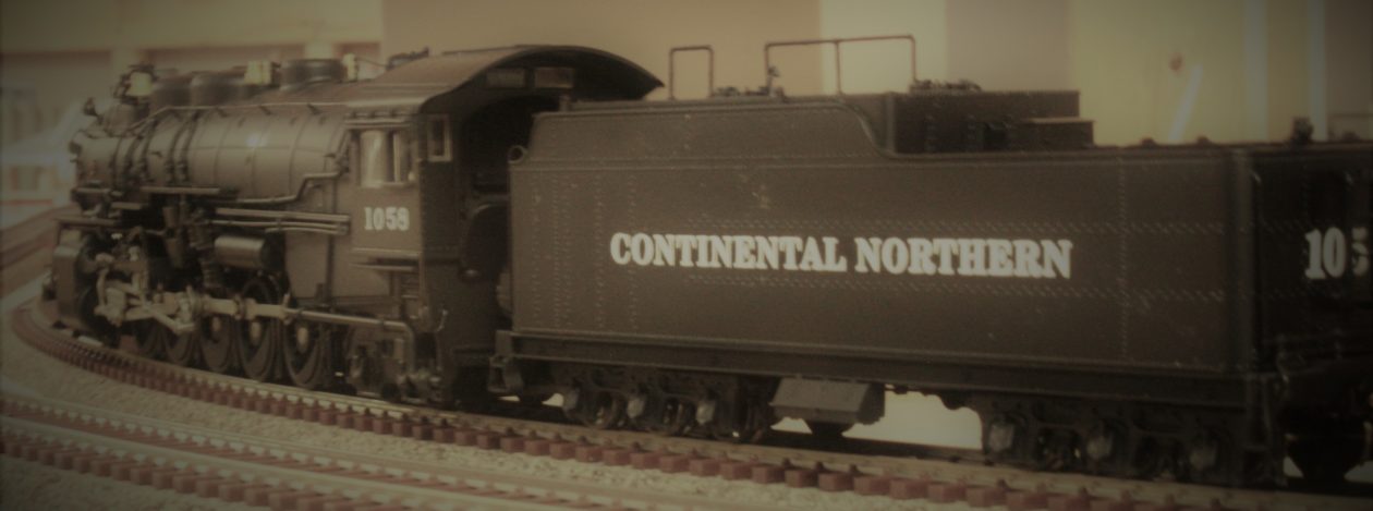
Got the helix started and we are movin’ on up to the second deck.
As I had left it last, I had all the curved roadbed pieces cut for the helix. As I was getting ready to assemble the first loop I realized that even if I got it put together I had no way to mount it. So back out to the garage to cut the vertical supports.
Originally I was going to have six sets of vertical supports. They would mate up with the with the joint in the roadbed pieces. I had a rather intricate plan for the vertical supports that would have been a lot more involved and labor intensive. Also I would have had to figure out how to a measure .667 inch rise between supports. I did the math and the fraction of an inch isn’t any better. So, I decided to have eight sets of supports, which meant that it would be a half an inch rise per support. A lot easier to figure out.
I than had to refigure the placement of the supports. Which presented the next hitch. One of the supports landed right in the middle of the reverse loop under the helix. Again, out to the garage to cut a piece to lift the support over the track.
The supports.


And then I was off and running. First I measured and cut off half of a curved section for my overlap. With that done it was a matter of gluing and screwing the pieces together till I had a complete circle.


Before I moved the finished ring to the layout I started the next loop so that the overlap would match up.

Ah yes, moving the loop to the layout. I had assembled the loop at the end of the peninsula. The plan was to slip it into place on the Brandon side. Wouldn’t go. So around the layout and up and over the New Brighton street scene. Got it partially into place and then back around the layout and into the helix center where I wrestled it into place.
The next task was to join it to the other sub roadbed. My plan was not to use any cork roadbed to increase clearance. This meant an offset joint. While trying to figure out how to cut a piece 5mm thick for the offset, it occurred to me to just use a piece of cork sheet.

Next I measured and mounted half of the loop, with the other half pulled high (you can see it in the picture above). This was so I could mount the first section of track where it was under the overlapping piece of the loop. I am using code 100 track in the helix. The reason is simple, I have a bunch of it sitting around from what I figure is about 25 years ago. Plus if I need more it’s cheaper than code 83. This meant a had to use transition pieces. They are from Walthers (walthers.com).

After that, permanently mounted the rest of the loop.


Next up was to add the track, wired in feeder wires and then the first train.

Now it’s back to the next loop. Keep you updated…
