Category Archives: Benchwork

Rebuilding The Staging Yard…

I figured it was time to get the staging yard up and running when I noticed that I had 4 freight trains and 1 passenger train sitting on the mainline. And if I wanted one off, I would have to manually remove it and put everything back into their boxes.

If you don’t recall, I had done a little downsizing of the layout. I removed a “visible” city yard and replaced it with the “hidden” staging yard. The new yard won’t technically be “hidden” anymore as it will directly connect to the engine service facility. I may end up doing some mild scenery work on the yard for photo purposes.

The yard itself is 8 tracks wide. Before it moved, there was a nice symmetry to it. Two track from the mainline came in centered and branched out to the other 6 staging tracks for a total of 8. The 8 tracks will still work, but because of the way the mainline now comes in I had to rework the whole switch end of the yard.

Rather than trying to describe it I’ll just show it to you.

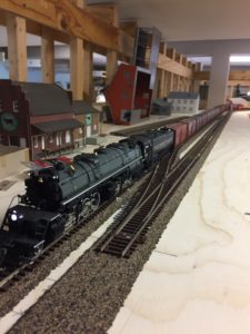
Looking at the new staging yard.
Putting the staging yard back together. Tracks on the left will be for engine and caboose storage. Looking towards the turntable/roundhouse area.

As you can see in the first picture each track get shorter with the track nearest the front more of a drill track then a storage track. It also serves the track heading into the engine servicing and roundhouse.

In the second image you can see the track running along the front of the layout. This is the one that runs to the turntable. It also branches out to three track that will be diesel storage / servicing tracks. May use one for caboose storage  / service.

Of course as I was working on this…

Squirrel …

I thought since I’m laying the track that is going  to connect to the turntable, I should work on the installation of the turntable and roundhouse.

The first thing was to locate the center of the turntable. After that was to then lay out the tracks that would radiate from it for the roundhouse and outdoor service/storage tracks.

Laying out track spacing for the roundhouse.

Once those were in I then located the service pit areas of the roundhouse. I would have to cut away the plywood for the service pits to sit in.

Cutting the slots for the inspection pits. Time consuming, but not difficult.

Not difficult but time consuming. On top of that, my oscillating cutter has a lot of miles on it and is starting to overheat with a lot of use. This meant that I would have to let it cool down every once in a while.

Slowly working at getting the roundhouse and turntable in place. Two more slots to cut the the inspection pits.

As the picture shows, progress is being made. As of this photo, I only had two more slots to cut. Those are done now, as well as the round hole for the turntable. As I was getting ready to start fitting this all into place…

Squirrel …

I realized that if I installed the roundhouse / turntable, I would have to reach over it to finish off the backdrop. So everything temporarily came to a halt on this project. What I envision for the backdrop is a  urban scene. Basically a bunch of the backsides of tall buildings. Some fences between them and the tracks and ballasting the track. I still need to get the backdrop hard board on the right side up. This would be just out of frame on the second picture. It also would hide the helix that is visible on this side.

Of course I’m sure you have already figured out what has taken me a while to figure out. And that is, you don’t need the backdrop finished in order to finish hooking up the staging yard tracks.

And that’s where I’m at. Finish hooking up the staging yard tracks. I have a little realignment to do in order to get the mainline hooked up to the staging yard ladder. After that, get everything wired up so that I can get actually use the thing.

Well, as soon as this happens, I’ll let you know.

Till next time, Happy Modeling…


What Started It All…

Before I move on with other projects done or in progress, I should give you a little history of what started it all. And no, I’m not talking about what got me going in model railroading, but rather what led to the slew of unfinished projects getting done.

A couple of things came into play that acted as a catalyst for the change that led to the projects. First was that the kids had tons of Lego sets as they grew up. Those sets ended up in pieces in a couple of large totes. One of my projects over the years has been to sort the pieces out by color and type. And with the help of various Lego based websites I have been reassembling the sets. I was looking for a place to display them.

Second was that the layout that I am working on now is not the layout that I would build if starting today. After the previous layout failed so miserably, I was determined to build a successful multi deck layout. Kind of a “failure is not an option thing”. Thanks dad. Also, ops sessions are becoming not a thing as it has become harder to get people together for whatever reason. If starting today I would probably go the Pelle Soeburg route. Staging yard, a town to switch and a couple of signature scenes for photography / railfanning.

The Change…

To solve the problem of wanting wall space for shelves and a little less railroad, I decided to do away with some of it. Looking at what was there I decide to do away with New Brighton yard and the area of Duluth that was above it. I would then slide the staging yard into the New Brighton space and move the wharf scene of Duluth into the Duluth “Docks” space on the upper level.

The sections going away.
The sections that are moving.

That meant that New Brighton and the Duluth Docks area were completely disassembled. The sections being moved were moved as 8′ sections.

Disassembly continues.
Removing New Brighton yard.

Once all the old bench work was out of the way I prepped the end wall. I used a sheet of 1/8″ hardboard to act as a backdrop for the end of the staging yard / Duluth wharf scene. The rest of the framing on the wall was removed.

Prepping the end wall .
And The Reason Why…

With the space ready it was time to move the base cabinets. Some of the stuff, mainly engines and cars, had to be removed to get to the mounting screws. That and lighten them up some. I’m sure you can see where this is headed, the last cabinet was the “project” cabinet. Things not scene in a long time.

Most of these are somewhere in the neighborhood of 25 to 30 years old. I have hauled all of them out many times, thought that today is the day. And then put them back. First, back to the project at hand.

Like I said the base cabinets were moved first.

Base cabinets going into the area of the former New Brighton yard.

Once in the framing went back in.

Reinstalling the frame work.

Then the plywood sections with the yard was reinstalled.

reinstalling the staging yard.
The staging yard going back in.

Then added the upper deck.

The upper level and upper valance frame work.

In addition I also added the upper valance over the upper deck with lights. Below are views of the finished scene and with the room lights on and the layout lights off.

Upper valance installed.
Room lights off.
With That Done…

With the layout sections moved (I still don’t have everything completely hooked up) I finished putting things back into there respected cabinets. But as I was reloading the project cabinet, I started to look at the different kits thinking someday I have to finish this or that. I mean everyone always talks about all the kits they have collected. Kind of a rite of passage. And at some point I decided today was the day. I’m not getting any younger.

And that is where we are at. Projects to follow.

Till then, stay safe…


Switching it up…

When I last left you, this is where I was at…

And on to the end of the line.

I had reached the upper deck and had enough plywood for the first “town” area after the helix. Like I had said this isn’t necessarily a town as it will be a sawmill scene with a hint of a town. The plan was to keep moving on with the track work on the upper deck.

Well, I have the plywood for the subroadbed, but no space to cut it. My daughter and her husband are kind of in between homes and there is a lot of furniture in the garage. I’m able to squeak a car into our 3 car garage. This has been the case since early May.

Wanting to move forward I decided to start installing switch motors. Seemed like something that would be relaxing, easy and fulfilling. I have been slowly collecting them and have 19 Tortoise switch motors (www.circuitron.com) on hand. Along with 3 Digitrax (www.digitrax.com) DS 64s.

Originally my plan was to start at the staging yards and just keep moving around the layout. However without a finalized plan for the New Brighton yard I decided to skip it and start at the berm scene.

First thing to do was to wire them up. I was originally going to use Acculite snaps (www.acculites.com) to hook up the Tortoises. Instead, I have a bunch of CAT 5 cable on which has 4 pairs of wire. Works out great as there are 8 wire hookups on the switch motors. The thought is that they are all wired if I wish to use the contact points in the future.

Anyways, got the CAT 5 cut and stripped. Then started soldering production line fashion. Made sure all terminals strips wired the same. I also made sure to note the order in the “Book Of Standards”.

One of the first nineteen switch motors wired up.
Switch motor wiring using CAT 5 cable.

And after a couple of evenings they were set to install.

First 19 switch motors wired up and ready to be installed on layout.

Just a side note. I have noticed when the “Experts” talk about building a multi deck layout, they say that you should start with the upper deck. The reason being that by installing the upper deck first it will be easier to wire the upper deck. After crawling around the lower deck installing these I would disagree. The lower deck is to low to sit in a chair and wire and just a little to high to lay on the ground. Where as the upper deck is about 4 1/2 feet off the ground. Easy to reach in and install and wire these puppies up.

Anyways, got them installed. But nothing to hook them to. So it was time to start pulling wire from the electrical cabinet to the switch locations. For crossovers I used two Tortoises instead of using Circuitrons Remote Tortoise Mount to drive both switch points. Even Circuitron acknowledges that cost wise it’s not much different, but it’s easier to use two tortoises.

Got the wires pulled and the switch motors hooked up.

Switch motors going in and wired.

Then it was time to get the DS 64’s in.

Next time the journey continues. Til then, Happy Railroading…


And I’m Back…

I am back, limping along, but back. Haven’t heard yet as to what happened with the picture thing or when it will be resolved, but I have come up with a work around for now. I am now using the camera on my phone, although some of those pictures are to big to upload. Anyways, good enough for an update although I don’t think the picture quality is as good.

As I had mentioned in my last post I have finally reached the upper deck(insert trumpets blaring or a chorus of angels). As I laid the track onto the upper deck into what will be a hint of a town, but mainly a sawmill scene, I realized that I needed electrical support. Which means I started pulling new buss wires for the upper deck. Which in turn means I had to wire new a terminal block in the electrical cabinet as the upper deck is on a different booster/PM42. Did that and then the big moment came, I ran the first train up the helix and onto the upper deck and…

Electrical Gremlin #1…

The train hit the gap between the top of the helix/lower level booster/1st PM42 and the upper level booster/2nd PM42 and everything shorted out. The breaker kicked in, cleared and then clicked out again, rinse and repeat. I quickly pulled the engine off the layout to stop the shorting and then shut everything down.

Before we proceed , a picture of the completed helix and the dreaded “gap”,

Wide view of the entire helix.
The top of the helix and also the junction of the two DCC boosters.


I then started the arduous task of tracing all of the wiring to see where I had screwed up. Finding nothing that was wired incorrectly, I turned to “The Google” . After several attempts, I finally hit the right combination of words and got the answer I was looking for. It was a service bulletin from Digitrax (digitrax.com)  (not sure if Digitrax calls them service bulletins, but, oh well). Turns out that the polarity on Digitrax boosters are not always internally wired the same. WTF!!! Their fix is to simply flip the wires to Track A and Track B on one of the boosters. HUH. You would think that a company would have something like this pretty much down pat. So, fighting everything I know and grew up with (remember my Father the Electrical Engineer/Rocket Scientist) I flipped the wires on one of the boosters and tried again.

The command station and booster rewired to eliminate shorts.

And viola! The train ran up the helix, through the gap and up onto the upper level, no problem.

First train up the helix.
And on to the end of the line.

I breathed a sign of relief. And then it hit me, if everything was working right, why didn’t just the helix shut down?  Why did the whole lower level go dark?

Electrical Gremlin #2…


Looking over the PM42’s I realized that they have five LED’s, four red to show which section has shorted and a green to show power on. Nothing was lit. So I grabbed the multimeter and checked the PS 12 power supply and it was showing it supplying .03 volts. That’s a problem. I headed on over to the LHS as I know there were always a couple in stock. They were out of stock, turns out someone had come in the day before and bought both. I had Bill order a couple for me. This is late Wednesday and I picked them up Saturday morning. Can’t complain about that type of service.

I had originally wired both of the boards to one power supply, however the new setup is each board has it’s own supply. Got them wired to the boards, plugged them in and I had one board lit and the other one wasn’t. The one that wasn’t lighting up was the older of the two from my last layout. Not sure if the problem was with the board or with something in the wiring of the edge connector, I turned of the power and pulled the board out. Power back on and the light on the new PS14 wouldn’t light, meaning there must be a short in the connector wiring.

Normally I would have then checked the wiring on the edge connector. However, if you remember back when I installed them they are a little buried behind cabinets and under bench work.

Below is a photo taken when they were installed. There is now bench work above this.

View of the connectors installed. A rather tight space.

Also in that post I had mentioned that although I only needed two connectors I had wired up four in case of future expansion or should I have a problem with one I was using. Turns out that was time well spent.

So I changed over  the wiring in the cabinet, plugged in the board and turned on the power…

PM42’s now properly wired and working.

As much as I hate having to go back and rework things, I am happy with the way everything turned out.

Next up, wiring headaches continued.

Till then, Happy Railroading…


The Helix Continued…

I hope everyone is having a great Holiday Season. While I have been busy with family and work, I have had a chance to continue on the helix. Just not as much as I had hoped. I guess that’s the way it goes.

I did get the second ring of the helix installed. Tracks in and wired and successfully tested. Which leads to some thoughts on the way helixes are monitored.

This has been and continues to be one of the great divides on using a helix. Many will tell you that they would never use one for a couple of reasons. First, they are a tremendous real estate suck. Yes, yes they are. I have devoted about 30 square feet to mine. That’s a lot of space, especially if you are working in tight quarters. Fortunately I have the space.

The second is, you can’t see what’s going on and have no idea if the train is even moving.

My solution to that one.

One could just leave the helix open so that you could see what’s happening. My sense of aesthetic won’t allow me to have this great big monster hanging out in the open. I don’t know, maybe we should chalk it up to OCD.

My plan is the following. First the progress.

Second loop of helix in.

You can see above that both tracks end in the same place. Not something that happens when laying track with two different diameters. They were cut off together because this is the end of the first detection block. There will be a three over three signal at the entrance to the helix top and bottom. The upper signal head will show occupancy for the first section as the train navigates up or down. The lower the second section. The operator will have the visual cue of the signals so that they know there is movement.

If this isn’t enough, I have a two camera monitor that the operator can watch.

Monitor and cameras for the helix.

You can choose between the two cameras or have a split screen of both. The cameras will be placed (I hope) so that one can see the entire helix as well as the upper and lower return loops. Will see how that works out. I had picked this up at Lowes years ago on clearance. When I got it home and played with it I really liked it. Went back to get another but they were gone. The newer security systems are way too expensive (my opinion) for what I need. Mainly because they all have DVR’s built in. Don’t need a replay of the train in the helix.

Any ways, my solution to the problem.

I did get the third ring assembled and set into place.

Third loop set in place.

One thing that struck me was, with only two loops, it didn’t strike me as a helix. With the third in place it now “looks” like a helix.

Still have several family functions to attend through new years, so there won’t be much work done downstairs. After the 1st though I should be back at it.

Till then, Happy New Year…


Movin’ on up…

Got the helix started and we are movin’ on up to the second deck.

As I had left it last, I had all the curved roadbed pieces cut for the helix. As I was getting ready to assemble the first loop I realized that even if I got it put together I had no way to mount it. So back out to the garage to cut the vertical supports.

Originally I was going to have six sets of vertical supports. They would mate up with the with the joint in the roadbed pieces. I had a rather intricate plan for the vertical supports that would have been a lot more involved and labor intensive. Also I would have had to figure out how to a measure .667 inch rise between supports. I did the math and the fraction of an inch isn’t any better. So, I decided to have eight sets of supports, which meant that it would be a half an inch rise per support. A lot easier to figure out.

I than had to refigure the placement of the supports. Which presented the next hitch. One of the supports landed right in the middle of the reverse loop under the helix. Again, out to the garage to cut a piece to lift the support over the track.

The supports.

Vertical supports added for the helix.
Alternate view of the vertical supports in place.
Of course there is always a special case.

And then I was off and running. First I measured and cut off half of a curved section for my overlap. With that done it was a matter of gluing and screwing the pieces together till I had a complete circle.

Start of the first loop of the helix.
The staggered joint.
First loop complete.

Before I moved the finished ring to the layout I started the next loop so that the overlap would match up.

Also made the first section of the next loop so that the joint would match up.

Ah yes, moving the loop to the layout. I had assembled the loop at the end of the peninsula. The plan was to slip it into place on the Brandon side. Wouldn’t go. So around the layout and up and over the New Brighton street scene. Got it partially into place and then back around the layout and into the helix center where I wrestled it into place.

The next task was to join it to the other sub roadbed. My plan was not to use any cork roadbed to increase clearance. This meant an offset joint. While trying to figure out how to cut a piece 5mm thick for the offset, it occurred to me to just use a piece of cork sheet.

The loop in place with the joint plate connected.

Next I measured and mounted half of the loop, with the other half pulled high (you can see it in the picture above). This was so I could mount the first section of track where it was under the overlapping piece of the loop. I am using code 100 track in the helix. The reason is simple, I have a bunch of it sitting around from what I figure is about 25 years ago. Plus if I need more it’s cheaper than code 83. This meant a had to use transition pieces. They are from Walthers (walthers.com).   

Added the track to the area under the end of the loop while still accessible.

After that, permanently mounted the rest of the loop.

setting the rest of the loop in place.
The loop from the other side.

Next up was to add the track, wired in feeder wires and then the first train.

Successful run up the first part of the helix.

Now it’s back to the next loop. Keep you updated…


Finally, The Helix…

I have finally taken the first steps towards starting the helix. It is long overdue. This past weekend I had a large block of time.  And since it was still warm enough in the garage without heating it I picked up the plywood and started cutting.

As I had mentioned before (it’s been awhile, May 2015) I have a aluminum pattern that I had made for the curves. Using the pattern I trace out the curve section on the plywood (I can get 16 curved sections on a 4 x 8 piece of plywood). I then rough cut out the pieces. Then again using the metal pattern screwed to the rough cut pieces I run them threw the router using a pattern bit. I had detailed this along with pictures in the May 2015 post if you want a better idea of how it works.

I need 12 curved sections per loop. Six would complete one loop if I were using 3/4″ plywood. However than you would have to join the pieces together without creating a clearance problem. My solution was to use 3/8″ plywood and laminate the pieces together offsetting the joints to crate a 3/4″ thick ring that would have nothing below to cause clearance issues.

The stack ready to go.

All loop pieces ready to go. Also 4 sections for the entrance and exit from the helix.

As noted there are also four pieces (bottom of stack) that I cut with straight sections leading into and out of the helix.

My plan is to assemble them away from the layout one loop at a time. I will glue, clamp and screw them together.  Then I will add that loop to the layout, lay and wire the track. I will then run a test train through it before going on to the next loop. After the first loop works I will repeat the process.

The thought of trying to mark the locations for screws and the center line of the track kind of boggled my mind. A little thought and my next great idea. Back out to the garage and in no time I made a couple of marking gauges.

They ride along the edge of the roadbed and have holes in them for a pencil to mark screw and track locations. One is for the inside of the curve and the other for the outside.

Tried one out and this is what it looks like.

I should have the first loop completed and installed this week. Will keep you updated. I will also have an update on the grain complex for you on Wednesday.

Till then, Happy Modelling…

A River Runs Through It…

As I had said the next part of the scenery had a river that runs through it. I had penciled in where I had wanted the river but never cut it out. Part of the reason was that I was unsure of what type of bridge. The track here in on an incline (slight) and a curve. And I didn’t want just a culvert.

I finally decided to use the sides of an Atlas (atlasrr.com) plate girder bridge. That way I could cut the sides of the plywood subroadbed flat on the side and add bridge abutments and presto, a bridge.

First up was to cut out the river. Not an easy task considering that everything else was in place and I had to be careful not to wreck what was there. Mainly I had to be careful of the wiring that ran underneath the area. This is where one of my favorite tools came into play. It’ my Dremel Max (dremel.com) oscillating cutter. With the wood  cutting head in It, you can come in real tight and have excellent control. So I got the river cut out.

The wall in place and the river cut out.

And then the next problem. Seems the feeder wires for these two tracks are right in the middle of the bridge.

Of course the feeder wires are in the way.

So these had to be moved. No big deal, but it seems it is always something.

With the wires moved it was on to the riverbed. I used 1/4″ plywood but wanted to add stiffeners so I could staple the screen to it. Problem here is there is little access. Because the cabinets are set back 6″ from the edge of the benchwork and wiring running underneath, you can’t come in from the bottom. the piece is too wide to come in from the top. And there is only a 3/4″ wide slot at the front. So I prepped the panel with all screw holes in place, slid the panel in and then added bracing.

The river base ready to install.

Next up was the abutment. My first version was the bridge support with the wings attached. Once done I slid them in place and decided that the wings where way to low.

Bridge abutment version 1.

The bridge abutments were built out of .040 styrene sheet and .100 styrene strip with some trim work to look like poured concrete. I cut the wings off so I had just a support. Then I built new wings that came up to the full height of the river bank.

Abutment wings for version 2.
Version 2.

Then I needed my plate girder sides. As I recall you used to be able to buy them separately as a flat car load. No joy there. I ended up buying a full bridge and cutting the sides off from it. Next thing was Atlas built there bridge around a 9″ piece of straight track, which scales out around 65 feet. My span was only 28 1/2 feet.

Bridge abutments in place. The plate girder sections will need to be resized.

A little too long. So working from the center I cut it apart. I used the short double reinforced sections from the ends and grafted them on to a cut down center section. The end results are near perfect.

The finished bridge set in place.

Then brought the screen down to the river and added the plaster cloth.

The scenery finished down to the river.
alternate view.

It just needs a top coat of plaster and it will be ready for some earth paint and then scenic materials.

That’s what I’ve got for now, until next time. Happy Modelling…


Staging Yard wired…

I also got the staging yard wired up. I know that I may have led you to believe that I had wired this up before when you saw the photo of a switch and LED lit in a previous post. What I had done was a quick hook up with jumper wires in that shot to see if things would work.

The staging yard is eight tracks wide with three to four 3ft sections of flex track per yard track. I wired each section of flex track individually to make sure there would be no dead sections because of a loose rail joiner. In another word there are a lot of wires pulled to the switches. I have a picture of all the wires pulled to a hole in the fascia, but it’s one of those that is sideways and for whatever reason can’t be corrected.

I then installed all the  switches and LED indicators in the fascia and wired those up before mating the fascia to the yard wires.

Back of the yard panel – wired and ready to hooked to the yard.

I should also note that before installing the switches and LED’s that I painted all the fascia panels and used RC striping tape to indicate the track.

I then joined the two and screwed the fascia in place.

Track power switches and indicator LED’s.

Side note: The reason for the oddness in the way the tracks are laid out in the diagram on the fascia is – I had six switches controlling six turnouts, thus when I laid out the track diagram I did it for six tracks. I didn’t figure out till after I drilled the first six holes for switches and LED’s that six turnouts feed into eight tracks. So the above layout is an effort to save the work I had into the fascia.

Along with the track numbers I also added the capacity of each track as measured in forty foot cars as they were most prevalent at the time.

UP-5 panel for the yard and the yard track numbers with track capacity in 40 ft car lengths.

I took the track diagram as far as the New Brighton yard as I have not completely figured it out yet. More on that at a later date. But the track diagram up to that point does include the hidden siding for the power plant. You’ll notice that the tracks for this siding are in yellow. My plan is to have the main in white and the sidings in a different color. At this time most likely in all yellow.

Track diagram of the staging yard on the fascia.
Staging yard lead is in white, the storage tracks for the power plant are in yellow.

Well that’s what I’ve got for now, Till later…


End of January Update…

It is the and of January and I have some actual progress to report on the railroad. First of all, for those wondering about the roundhouse, progress on it is as far as it can go until it is set in place. And when that will happen is a whole post on it’s own.

So what have I gotten done. Well, as I mentioned at the beginning of the month, I had cut a whole bunch of wood so that things could get done. First the “power box” that I touched on in that post.

I have been reading in multiple blogs and forums that one should be able to kill the power to the whole railroad should something happen. Add to that all the extension cords and power strips I had everything hooked up to, I figured I should do something. My answer was a box that would control power to the deck lights, aisle lights, blue rope lights for night lighting and all the power to the DCC system and related equipment.

It is simply a box tucked into the one of the electronic cabinets that has power to it, with switches on the front for the different functions and outlets on the back for the related items. Here is a photo of the finished box in place.

Main power panel – light control as well as all power to the layout.

It wasn’t hard to do, just a little time consuming, but I already feel it has been worth it as I used to have to plug in two cords to get the deck lights on in order to work on things on the lower deck. Now, I just flip a switch.

Next was the missing backdrop sections. Those installed were: The short section near the power station between the staging yard and the power station, behind the roundhouse and behind the berm scene.

Scenic block between layout and staging yard.
View from the staging yard.
Backdrop behind the roundhouse scene.
Backdrop in place behind New Brighton berm scene.

I have one section left on the lower level which is on the backside of the berm scene. I have the piece cut but have not installed it yet. The gaping hole between the piece behind the roundhouse and the berm scene is where the helix will be. Its backdrop won’t be installed until it’s installed.

The next thing I have been working on has been the fascia around the lower level. I had started with the piece under the staging yard and have been working my way around. I have it in place all the way up to the town of Jackson. However, I stopped just outside of town as I’m trying to figure out some of the scenery contours and need to figure out how wide to cut the next piece to accommodate a hill that acts as a scenic block.

Fascia in place in the back aisle. Holes cut for UP5 panels.
Fascia installation working it’s way around layout.

I also have mounting the UP5 panels for the DCC system to the fascia. I made a mounting template out of styrene to mark screw hole location and the hole for the circuit board. Fun to make and it makes it easier to mark the holes and keeps things consistent.

UP5 template I made to speed up the hole process.
Hole cut for the UP5 panel.
UP5 panel mounted.

Lastly, the first set of doors are done and installed. These are on the side that faces the stairway up to the family room. Since there is no door that would block the view of the unfinished layout, it has been my wife’s biggest bug-a-boo and why she wanted them in.

First set of cabinet doors finished and installed.
View of the layout from the family room. This is why my wife wanted the doors on.

As I said this is the first set, only 25 more doors to make. But the heat is off to get them done.

So looking back at January what have I learned. Probably the same thing you had noticed, that after several months of not being able to work on anything major downstairs, I was all over the board trying to get everything done. Time to sit back and take stock of where I’m at and organize where I’m heading.

Till next, Happy Railroading…