Category Archives: Wiring / Electronics

Wiring for Lights…

The quest for lights in the buildings took a multi prong approach. I have some buildings with regular 12/14 volt lights in them. The 14 volt lights are a preference as they glow a little dimmer and last longer, but I have more 12 volt bulbs. It tends to be whatever is on hand as I do them. Also, I have started to use LED’s that I have scrounged from Christmas tree strings. In addition to these traditional routes I have been buying the Woodland Scenics  Just Plug Lighting System.

The Woodland Scenics System

Here is the collection of Just Plug lighting products I have collected.

Getting all the electrical supplies together for lighting for the Addison scene.
Lighted cars and billboards.
More of the lighting supplies.
Lighting supplies, wire, LED lights, cables, etc.
A couple of cars near the farm scene.

The cars, billboards and street lights make it very easy to get up and running. Although the wire size is extremely small. It does try ones patience when working with them. Also the controllers make adjusting the light levels to a realistic level easy.

The 12 volt supplies

Up until now I have been using 12 volt wall warts as power supplies for everything not track power. Though they work you start ending up with a large hodge podge of different power supplies that really gets confusing as to whats doing what.

My solution was a couple of regulated 12 volt power supplies that will get rid of all the wall warts. The ones I bought are from Micro Mark and are used for LED string light.

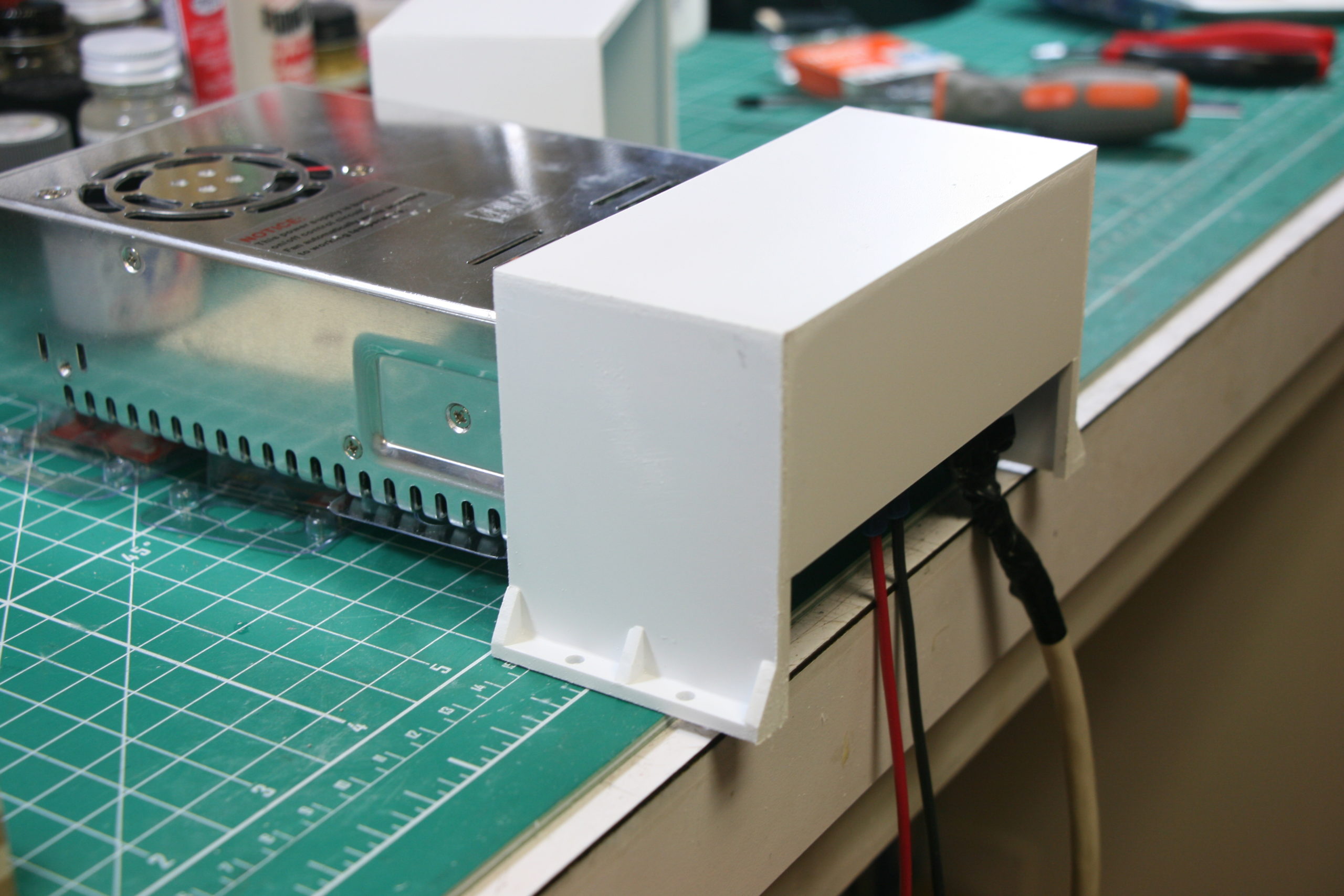
The only problem is that I believe they are intended as an internal power supply and the connections for 120 volt power are rather exposed.

Wiring up the power supply. The 120v connections are rather unprotected.
The power supply wired up with the protective cover in place.

As you can see there is a plastic strip that “covers” the wire connections but it would still be easy to accidentally touch the connections. My solution was to make a larger cover out of styrene to cover the whole end.

The covers for the power supplies.
Showing the cover in place.

With the covers made and before installing in the electrical cabinet I checked the output voltage.  Both were a little over 12 volts. They are adjustable, so I hooked up a multi meter and dialed them in to 12 volts.

The power supply dialed into 12 volts.

From there it was time to reinstall them in the cabinet.

The power supplies and block installed. waiting for the second distribution block to arrive.
The fused distribution block.

I also had found a power distribution block on Amazon that was fused for each feed. On the one cover you can see that I labeled it with the information about the power supply so that it was readily available should I need the info. The upper supply is for lighting , while the other will be used for accessories. With these in place I ran a buss wire for the lighting and also a wire from the Woodland Scenics power supply to Addison.

Woodland Scenics light hubs on the left, Standard 12V DC on the right.

Then it was just a matter of pulling all the different wires to the blocks.

Wires all connected.

With these in place it’s easy to add more lights as I add to the town. I still have the background buildings to place and wire. I will also be doing the same for the lights in Jackson.

And the final results…
End of the day at the farm.
Two cars passing in the night.
“Why no officer, I wasn’t aware I was going that fast.”
Downtown Addison at night.
Gas station and depot, the Northbound just pulled into town.
Overall shot of Addison.
The depot scene, the order board is showing green.

And there you have it. It’s nice to have this much done. Obviously the next thing here is to add more scenery as only the basics are in. Also, I am starting to work on the background buildings, which will be a whole new bunch of lights to wire up. Also looking at the photos I need to get the rest of the backdrop panels in and close up that really ugly hole. And in case you are wondering if you missed something, the answer is no, I have yet to finish up the town of Jackson on the other side of the peninsula. I just wanted to get the scene you see on entering finished.

That’s what I’ve got for now, till later…


Back On Track…

Yup, I’m back on track. OK, enough with the stupid puns, I promise. I was able to get back out to the garage and get the plywood cut for the subroadbed  curve around the end of the peninsula. How was this possible? I was finally able to get  rid of the Candy Cart. Insert happy dance here. With it out of the way I have room to get things done now.

The cart went away around the end of October. With it gone I shifted into high gear. My goal was to have track in and wired on the upper deck up to and including the upper reverse loop by Thanksgiving. That way I could orbit a couple of trains. My family loves to see the layout and to see the trains run. However, watching a train run to the end of the finished track and stop just doesn’t cut it. I have learned that unless you’re into model railroading  you want to see trains running. Even if it’s a big circle.

With that in mind I got to work. I installed the curve around the end of the peninsula and the plywood for what will be “Interstate Junction”. Side note, I will have a post in the near future explaining the “Junction”.

Upper mainline around peninsula end in place.

Laying out the “Junction” required working out the return loop first. How the return loop lies determines where the track cuts off the mainline.

As I had mentioned before, the return loop crosses the mainline as it comes out of the helix. So that is where I started.

Upper helix lead. Return will crossover here and hide entrance to helix.
Laying out return loop.

With this laid out I added the support structure for the return loop subroadbed.

Planned bridge scene that will hide helix entrance.
Return loop over helix started.
Longer view of return loop entrance over helix.

The plan was for the loop to meet back up just past the bridge to head back out to the mainline. However I had clearance problems. The return loop ended up climbing a bit over the end of the helix. I had to run the loop down the other side of the divider before meeting back up.

Working on the return loop exit from over helix.
Laminating the subroadbed for the return loop exit.

Once I had this part laid out I went back and laid out the mainline track work and where the loop branched off.

Working from the junction to the return loop.
Approach track from junction to bridge scene.

And then it was just a matter of piecing everything together. Once done I started adding the cork roadbed.

Working on the track placement for Interstate Junction.
Cork in place and ready for track.

After the cork was in place it was on to the track and wiring.

Track in place for Interstate Yard.
Alternate view of junction.
Closer view of “The Junction”.
Track work in place for return loop.

I have kept all grades (the amount of rise or fall of the track) to 2% or less. Because of the climb over the end of the helix, the return loop drop is closer to 3%. I don’t see this as a problem because trains are traveling counter clockwise and the 3% is downhill.

Anyways… once the track was in and wired it was time.

First train headed into upper return loop.
Around and over upper helix lead.
And back out of the loop.

I was thrilled to have gotten this done. It has been a long time goal and now I’m there. Of coarse it was not problem free. When I wired in the lower return loop with the Digitrax (digitrax.com) AR-1, the return loop worked flawlessly. With the second wired into the upper loop I now have a problem. The first train entering each return loop (upper and lower) trips a breaker, pauses and then goes on. After that no more problems. Only thing at this time I can think of is to tweak the trip current on the AR-1’s.

AND this was all done Thanksgiving Eve. Trains ran beautifully on the big day.

With this done, I’m now able to let the trains run. Where this is important is getting all the engines out and running. They’ve been in storage for way to long. I’ll be able to see which are fine and which will need some TLC.

And that’s it for now. Till later…


Switch Machines Pt. 3 …

Since I have the switch machines installed, wired up and programmed I thought I was set. Using my new found power to throw switches on demand, I was feeling pretty good about all the crawling around underneath the layout hooking them up. Went to grab another local freight from the staging yard and found I had a problem.

Digitrax’s (digitrax.com) DT throttles are full function. Their UT (utility) throttles are not. Which means that an operator, usually the yard operators, are unable to throw a switch from their throttles. Not  wanting to scrap the UT throttles and replace them with DTs (hello, they are expensive) I was going to have to do something.

Turns out that “something” isn’t that difficult.

My plan has been to use the fascia as a “kind of” control panel. Like I had done  with the staging yard, the towns will be laid out with striping tape. White for the main lines and the sidings in yellow. Industries will have their names and car capacities labeled. The number for the switches would also be by the turnout. Also kicked around adding LEDs for turnout indication.

The plan was to do this as time permitted. But the need for a way to control the turnouts locally moved the project front and center. In addition to the above I added a momentary push button switch to the panel at each turnout location. The DS 64s have additional input capabilities for just this situation.

Of coarse this meant pulling more wires. but one does what needs to be done. And actually with the roll around wire rack this really isn’t work, just time consuming.

The solution in pictures:

Fascia with industry labeled. Track capacity number is also on the fascia.
Fascia with the switch numbers in place. Holes for push buttons and LED indicators.
Fascia going in place, push buttons and LEDs installed.
Fascia in place.

Don’t have a shot of them lit up (the LEDS, not me), but I will try and get one for the future. The LEDs are powered through the DS 64 and the red (for a thrown turnout) is not as bright as I would like, but the green is. And when you are rolling through town with a hot freight green is what you’re looking for. If I wanted to as a future project, I could rewire the LEDs through the extra contact points on the switch machines, but for right now they are fine.

So Jackson has it’s switch machines in place with control from either the throttle or the fascia. For right now its a lot of fun switching the town, though I’m sure that it wear off after a bit. Which is a bit sad.

For now that’s it, next time we switch gears again. Till then Happy Modelling…


Switch Machines Pt. 2…

Having installed the switch machines, it was now time to add power and control. As I had mentioned before, on the last layout I only used the DCC system for locomotive control. When I started  this layout I was determined to use more of is capabilities.  That means the switch machines will be controlled from the throttles as you walk around.

So to do that meant the installation of Digitrax’s (digitrax.com) DS 64 stationary decoders. Not a big deal, as I was collecting switch machines I was also collecting DS 64s. They are mounted in the electrical cabinet (if it’s electronic , it’s in the electrical cabinets), the initial question was how. If I mounted them on the back or side wall, access for wiring, programming and maintenance would be a hassle.

The solution (and my original plan that I wasn’t sure would work) was slide out panels. That way I could pull the panel out and sit in the aisle to wire or whatever.

I cut the panels  (I made two) to size. Using templates of the DS 64s I laid out placement. Then added in where the wire runs would be and added in cable holders.

Laying out the panel.
Laying out the panel with decoder location and wire looms in place.
Panel for the switch stationary decoders ready for the DS 64’s. All mounting holes for the decoders and wiring looms are drilled, with the decoders numbered for switches controlled.

I then mounted the DS 64s and the wire looms and they were ready to slide into place.

First set of DS 64’s mounted on panel and ready for the layout.

Once in place it was a matter of pulling the wires and then the long process of hooking them up.

DS 64’s mounted and panels slid into place.
The DS 64’s mounted with the wires pulled and ready to be hooked up.
First set of DS 64’s in and wired, ready to be powered up and programmed.

With that done it was it was time to start programming the decoders. I had watched the video from Digitrax several times. Though it looked straight forward, I figured that meant that it wasn’t. Turns out it actually is as simple as Digitrax says it is.  With the switch motors wired and programmed I went around to make sure they all worked properly. A couple of them were working opposite of what they were supposed to be doing. It was a simple matter of reversing the wires to set that straight.

Now, you would think that this was the end of this story. Turns out there is more.

Next time the saga continues, till then… Happy Modeling…


Switching it up…

When I last left you, this is where I was at…

And on to the end of the line.

I had reached the upper deck and had enough plywood for the first “town” area after the helix. Like I had said this isn’t necessarily a town as it will be a sawmill scene with a hint of a town. The plan was to keep moving on with the track work on the upper deck.

Well, I have the plywood for the subroadbed, but no space to cut it. My daughter and her husband are kind of in between homes and there is a lot of furniture in the garage. I’m able to squeak a car into our 3 car garage. This has been the case since early May.

Wanting to move forward I decided to start installing switch motors. Seemed like something that would be relaxing, easy and fulfilling. I have been slowly collecting them and have 19 Tortoise switch motors (www.circuitron.com) on hand. Along with 3 Digitrax (www.digitrax.com) DS 64s.

Originally my plan was to start at the staging yards and just keep moving around the layout. However without a finalized plan for the New Brighton yard I decided to skip it and start at the berm scene.

First thing to do was to wire them up. I was originally going to use Acculite snaps (www.acculites.com) to hook up the Tortoises. Instead, I have a bunch of CAT 5 cable on which has 4 pairs of wire. Works out great as there are 8 wire hookups on the switch motors. The thought is that they are all wired if I wish to use the contact points in the future.

Anyways, got the CAT 5 cut and stripped. Then started soldering production line fashion. Made sure all terminals strips wired the same. I also made sure to note the order in the “Book Of Standards”.

One of the first nineteen switch motors wired up.
Switch motor wiring using CAT 5 cable.

And after a couple of evenings they were set to install.

First 19 switch motors wired up and ready to be installed on layout.

Just a side note. I have noticed when the “Experts” talk about building a multi deck layout, they say that you should start with the upper deck. The reason being that by installing the upper deck first it will be easier to wire the upper deck. After crawling around the lower deck installing these I would disagree. The lower deck is to low to sit in a chair and wire and just a little to high to lay on the ground. Where as the upper deck is about 4 1/2 feet off the ground. Easy to reach in and install and wire these puppies up.

Anyways, got them installed. But nothing to hook them to. So it was time to start pulling wire from the electrical cabinet to the switch locations. For crossovers I used two Tortoises instead of using Circuitrons Remote Tortoise Mount to drive both switch points. Even Circuitron acknowledges that cost wise it’s not much different, but it’s easier to use two tortoises.

Got the wires pulled and the switch motors hooked up.

Switch motors going in and wired.

Then it was time to get the DS 64’s in.

Next time the journey continues. Til then, Happy Railroading…


And I’m Back…

I am back, limping along, but back. Haven’t heard yet as to what happened with the picture thing or when it will be resolved, but I have come up with a work around for now. I am now using the camera on my phone, although some of those pictures are to big to upload. Anyways, good enough for an update although I don’t think the picture quality is as good.

As I had mentioned in my last post I have finally reached the upper deck(insert trumpets blaring or a chorus of angels). As I laid the track onto the upper deck into what will be a hint of a town, but mainly a sawmill scene, I realized that I needed electrical support. Which means I started pulling new buss wires for the upper deck. Which in turn means I had to wire new a terminal block in the electrical cabinet as the upper deck is on a different booster/PM42. Did that and then the big moment came, I ran the first train up the helix and onto the upper deck and…

Electrical Gremlin #1…

The train hit the gap between the top of the helix/lower level booster/1st PM42 and the upper level booster/2nd PM42 and everything shorted out. The breaker kicked in, cleared and then clicked out again, rinse and repeat. I quickly pulled the engine off the layout to stop the shorting and then shut everything down.

Before we proceed , a picture of the completed helix and the dreaded “gap”,

Wide view of the entire helix.
The top of the helix and also the junction of the two DCC boosters.


I then started the arduous task of tracing all of the wiring to see where I had screwed up. Finding nothing that was wired incorrectly, I turned to “The Google” . After several attempts, I finally hit the right combination of words and got the answer I was looking for. It was a service bulletin from Digitrax (digitrax.com)  (not sure if Digitrax calls them service bulletins, but, oh well). Turns out that the polarity on Digitrax boosters are not always internally wired the same. WTF!!! Their fix is to simply flip the wires to Track A and Track B on one of the boosters. HUH. You would think that a company would have something like this pretty much down pat. So, fighting everything I know and grew up with (remember my Father the Electrical Engineer/Rocket Scientist) I flipped the wires on one of the boosters and tried again.

The command station and booster rewired to eliminate shorts.

And viola! The train ran up the helix, through the gap and up onto the upper level, no problem.

First train up the helix.
And on to the end of the line.

I breathed a sign of relief. And then it hit me, if everything was working right, why didn’t just the helix shut down?  Why did the whole lower level go dark?

Electrical Gremlin #2…


Looking over the PM42’s I realized that they have five LED’s, four red to show which section has shorted and a green to show power on. Nothing was lit. So I grabbed the multimeter and checked the PS 12 power supply and it was showing it supplying .03 volts. That’s a problem. I headed on over to the LHS as I know there were always a couple in stock. They were out of stock, turns out someone had come in the day before and bought both. I had Bill order a couple for me. This is late Wednesday and I picked them up Saturday morning. Can’t complain about that type of service.

I had originally wired both of the boards to one power supply, however the new setup is each board has it’s own supply. Got them wired to the boards, plugged them in and I had one board lit and the other one wasn’t. The one that wasn’t lighting up was the older of the two from my last layout. Not sure if the problem was with the board or with something in the wiring of the edge connector, I turned of the power and pulled the board out. Power back on and the light on the new PS14 wouldn’t light, meaning there must be a short in the connector wiring.

Normally I would have then checked the wiring on the edge connector. However, if you remember back when I installed them they are a little buried behind cabinets and under bench work.

Below is a photo taken when they were installed. There is now bench work above this.

View of the connectors installed. A rather tight space.

Also in that post I had mentioned that although I only needed two connectors I had wired up four in case of future expansion or should I have a problem with one I was using. Turns out that was time well spent.

So I changed over  the wiring in the cabinet, plugged in the board and turned on the power…

PM42’s now properly wired and working.

As much as I hate having to go back and rework things, I am happy with the way everything turned out.

Next up, wiring headaches continued.

Till then, Happy Railroading…


Workshop Wednesday…

Welcome to Workshop Wednesday. I know that the prevailing trend is for a Wordless Wednesday, but I don’t have  a bunch of cool or thought provoking pictures on hand for this. If you can’t get your head wrapped around this skip the text and just look at the pictures.

So I decided to go in a different direction. My first project for this was a new way to handle all my wire for projects. What my solution for this was  DIY cart that mimics those used by commercial electricians. So the design isn’t anything new, just something I could make with materials on hand.

In the past I used a three tier cart from Ikea (ikea.com) that I had mentioned in a previous post. Great for holding everything, but not when you needed to actually pull wire. I had to find a way to hold the wire so it would unroll as I pulled it through the benchwork. Plus I had a couple of big rolls of flat phone cable for DCC wiring that wouldn’t fit on the smaller cart.

So working from memory I made my own wire cart from scrap material. The only thing I had to buy were the rubber coated casters. I wanted the rubber ones so that they wouldn’t mar the floor and the cart wouldn’t move when pulling wire.

So this is what I had:

The old electrical Cart.
And more wire that didn’t fit on the cart.

This is the new cart:

The new electrical cart.

And this is it loaded up:

With the wire loaded on it.
The other side and a view of the top tray.

As you can see I have enough room for everything on hand, plus room for more. Plus, the tray on top is larger then what I had with the Ikea cart. One thing I will probably do is somehow fasten the soldering iron base so that it stops tipping over whenever I pull the iron from it.

Pulling wire for whatever project I was working on was never something I looked forward to. But now I’m actually looking forward to it . And I do have a couple of them coming up.

Have a great week. Till later…

Staging Yard wired…

I also got the staging yard wired up. I know that I may have led you to believe that I had wired this up before when you saw the photo of a switch and LED lit in a previous post. What I had done was a quick hook up with jumper wires in that shot to see if things would work.

The staging yard is eight tracks wide with three to four 3ft sections of flex track per yard track. I wired each section of flex track individually to make sure there would be no dead sections because of a loose rail joiner. In another word there are a lot of wires pulled to the switches. I have a picture of all the wires pulled to a hole in the fascia, but it’s one of those that is sideways and for whatever reason can’t be corrected.

I then installed all the  switches and LED indicators in the fascia and wired those up before mating the fascia to the yard wires.

Back of the yard panel – wired and ready to hooked to the yard.

I should also note that before installing the switches and LED’s that I painted all the fascia panels and used RC striping tape to indicate the track.

I then joined the two and screwed the fascia in place.

Track power switches and indicator LED’s.

Side note: The reason for the oddness in the way the tracks are laid out in the diagram on the fascia is – I had six switches controlling six turnouts, thus when I laid out the track diagram I did it for six tracks. I didn’t figure out till after I drilled the first six holes for switches and LED’s that six turnouts feed into eight tracks. So the above layout is an effort to save the work I had into the fascia.

Along with the track numbers I also added the capacity of each track as measured in forty foot cars as they were most prevalent at the time.

UP-5 panel for the yard and the yard track numbers with track capacity in 40 ft car lengths.

I took the track diagram as far as the New Brighton yard as I have not completely figured it out yet. More on that at a later date. But the track diagram up to that point does include the hidden siding for the power plant. You’ll notice that the tracks for this siding are in yellow. My plan is to have the main in white and the sidings in a different color. At this time most likely in all yellow.

Track diagram of the staging yard on the fascia.
Staging yard lead is in white, the storage tracks for the power plant are in yellow.

Well that’s what I’ve got for now, Till later…


End of February update…

Hi, it’s been a bit, sorry about that. In this end of February update I’m going to cover a few things. So here goes…

First – Picture problem fixed.

Actually I’m not sure there was an actual problem, I’ll explain. I got a new camera as my old one was getting outdated. If only in terms of current technology. It’s an old Canon Rebel XTi with a 10 megapixel sensor. A great camera that’s still working perfectly. But because  I use the camera for work too, it could be better. So I got a new Canon Rebel T6i that has a 25 megapixel sensor and a faster processor. Figured I could shoot better (more detailed) pictures of the layout, plus I can shoot video with it also. Turns out the website didn’t like the larger pictures, 10mb with the new camera as opposed to 3mb with the old. So for this post I shot the pictures with the old one. It was that or I had to “dumb” down the new camera. Any way, as I said, problem solved.

Second – The “speed bump”.

As I had mentioned in an earlier post, before I wired the track I had down, I had run into a speed bump. It was quite literally a speed bump. As I was laying track from the turnouts from the reverse loop to the yard at New Brighton over the bridge in the berm scene, I failed to notice a bump in the tracks at the end of the bridge. It was only as I was pushing a string of cars over the tracks that I had laid that I found the problem. There was a 1/4″ rise in the tracks over a 6″ length of track. A 1/4″ rise means the cars uncouple, not good.

The evil "speed bump".
The evil “speed bump”.

Turns out that I failed to screw down the plywood base that this end of the bridge was mounted to and the plywood had a slight warp to it. I know that I had looked at the plywood sticking up and had thought that I would have to do something about it, but my brain never made the connection. So I had to pull up the track, the roadbed and the subroadbed to fix the problem (that’s why I went ahead and wired the rest of the track and came back to this). Any ways I have fixed the problem.

The arrow shows the joint that had to be leveled in order to level the tracks.
The area that had the "speed bump", now repaired.
The area that had the “speed bump”, now repaired.

Third – Track down and wired.

Just so you know, I haven’t been sitting on my behind. I have the return loop in and wired. Held my breath, as I have never used an auto reverser (the AR-1) before, ran a train through it and it worked perfectly.

View of the berm scene with the return loop in the background.

Next, I laid the track from the switches to the staging yard and wired them up.

The Loop around the engine facility into the yard.
Beginnings of the yard at New Brighton.
The small stock yards and meat packing plant.

I only have the “main line”  laid through the yard as I have yet to figure out the rest of the yard. The background buildings are temporary, as I have yet to figure out their  placement.  The stockyards/meat packing plant is important because if I had not talked about it before, New Brighton had the largest stockyards west of Chicago and needed to be included.

The last “industry” in the yard is the power plant. It hides the hole  from the staging yard to the “real world”. I had planned on a single hidden track in the staging area for it, but found that I could put two tracks (switched) into the space.

The power plant that will hide the hole to the staging yards.
The throat for the staging yards and the hidden track for the power plant.

So there you have it. I can now run a train from the area just before the staging area to the town of Brandon or from Brandon south through the return loop and back to Brandon.

What’s next? Wiring the staging yard. Only a deal because each track will have a switch to turn it off so as not to have a bunch of sound equipped engines idling away. Then, laying the track in the town of Brandon itself. After that? It’s on to the helix and the upper level.

Wow, for some reason the upper level never seemed to be on my radar. How cool is that.

Till next time, Happy Railroading…


The Trains Are Running…

Yes, that’s right, the trains are running. Actually, they were running shortly after we got back from Milwaukee. However, I’ve been banging my head against the desk for the last week trying to upload pictures of the historic event to my website to no avail. I also shot a short video so that you could actually see it, but the file was too big to upload even if I could. If you want to see it, it’s available at my instagram account, same name.

As I left it several posts ago, I had wired the feeders and pulled them to the front. As I started wiring them to the buss wires, I was thankful that I had drilled all the holes for the wiring. The buss wires were perfectly located for soldering the feeders. It was a little dark under the edge until I realized that instead of just working around the rope light that installed for aisle lighting, I could plug them in and behold, a well lit space that made it easy.

After they were all wired, I cleaned all the tracks with a brite boy and was ready to roll. Then I realized that my DCC station was at the end of the stretch that I had wired and I would be unable to follow the train. So I temporarily mounted several UP-5 panels along the front, got them hooked up and THEN I was ready to roll.

I dug out a BLI 2-6-6-2 locomotive, why, it’s an articulated locomotive and it had sound. Got it on the tracks, turned on the power to the DCC system and stared at the throttle. Yup, it took me a few seconds to remember how to power everything up. But when I did and heard the sound come up on the engine, I was pretty sure you could hear a chorus of angels. It was a glorious moment. Turning the knob, the engine started moving and no, there is not a downside coming. Everything ran perfect. I added a dozen boxcars behind it and ran it back and forth over the twenty feet of track without any problems. Yay.

So there you have it, the trains are now running.

Now to complete the reverse loop and I can double the length of a run ( yes, I picked up the AR-1). Then get the tracks laid up to the New Brighton yard. I also now have the sheets for the yard, so that can be started too.

Hopefully I’ll get the picture problem worked out before next time.

Till then, Happy Railroading…