Once again scenes from the old layout. I promise to have an update in the next couple of days.


Once again scenes from the old layout. I promise to have an update in the next couple of days.
I have got some work done on the layout and will post some pictures in the next few days.
Meanwhile found some construction pictures of the ore boat and a dairy complex that never had a home.


Just got back from a trip, thus still no progress to report. Hope you enjoy the pictures from the past.
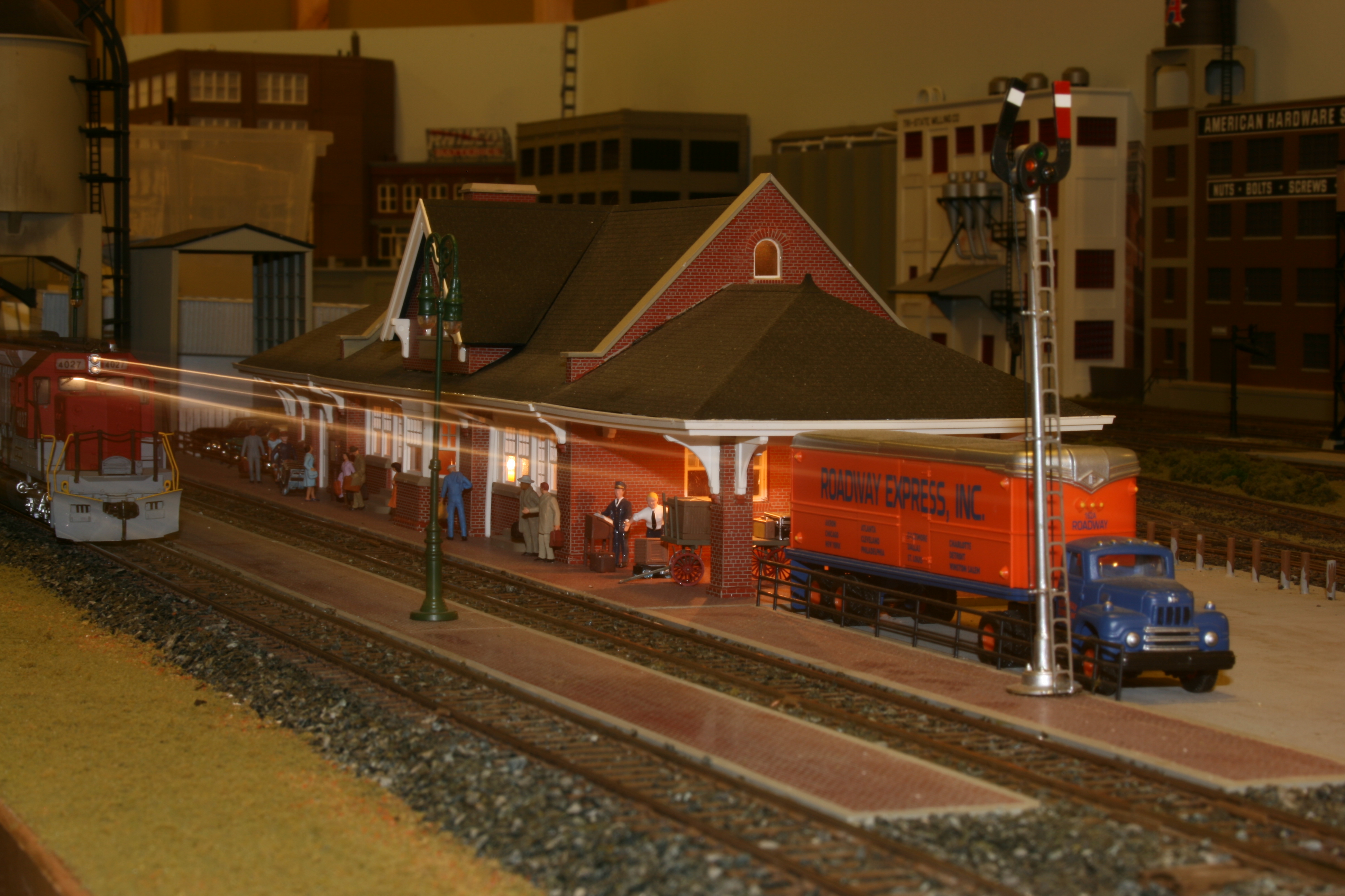
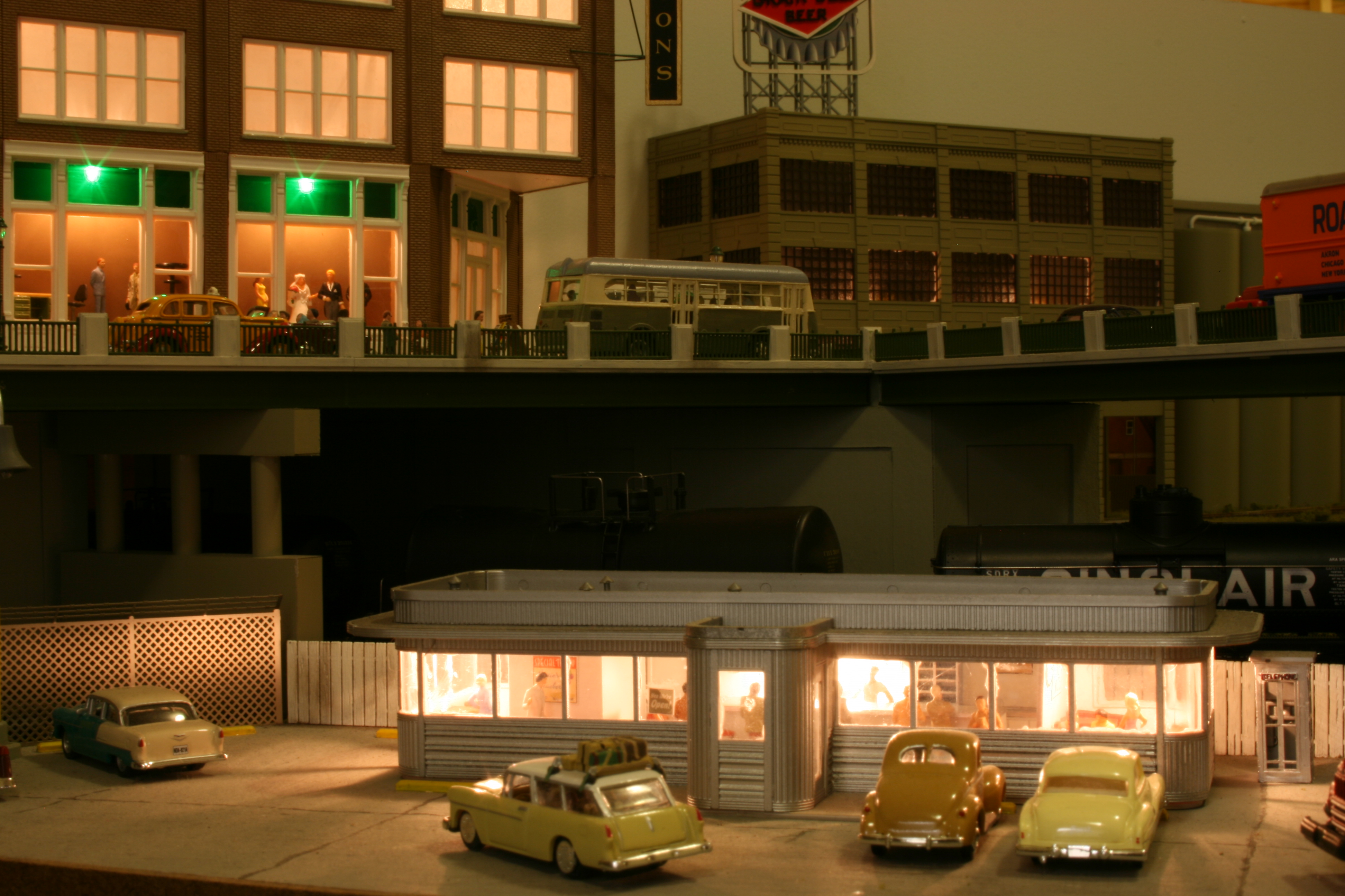

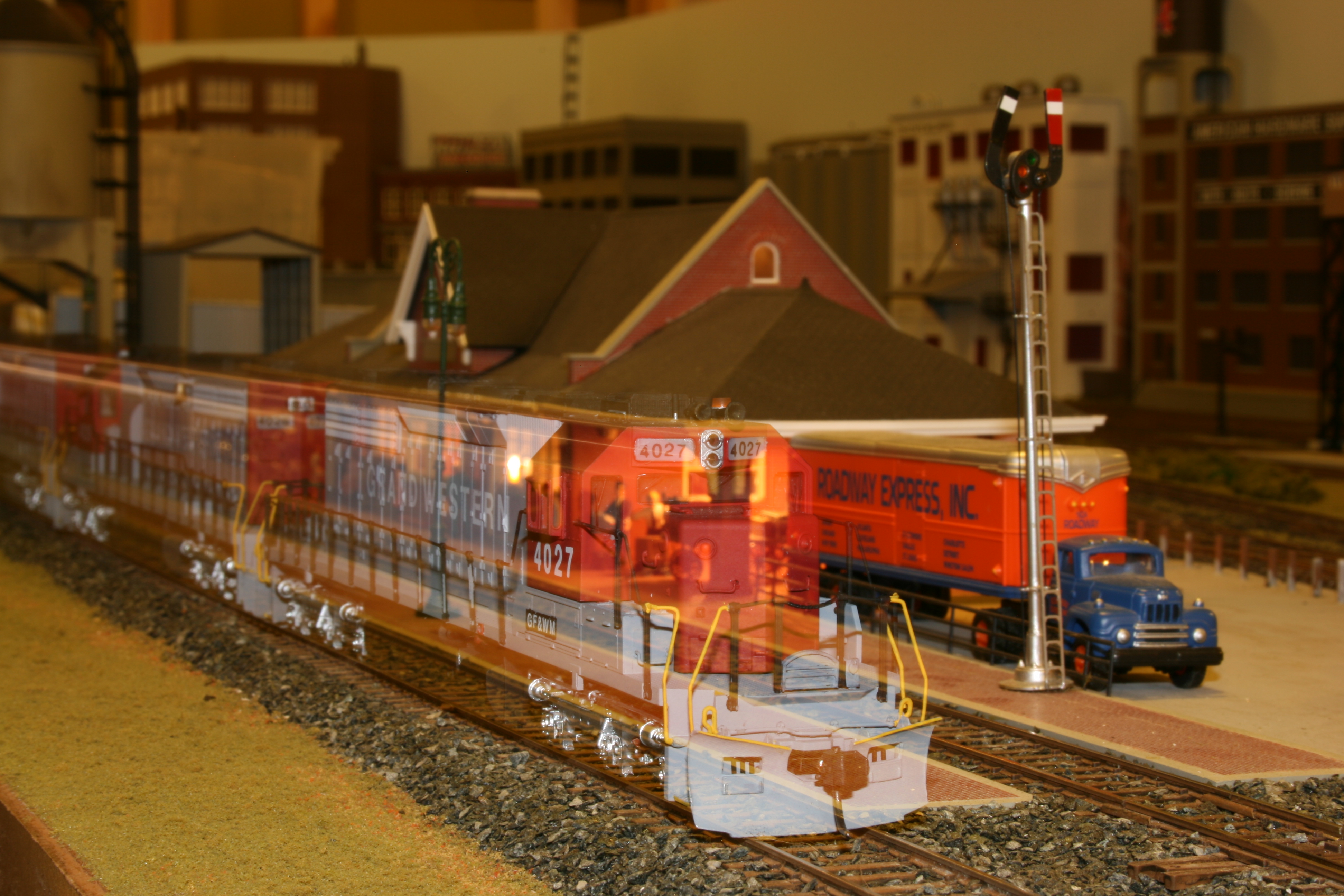
I have made a little progress on the railroad, however nothing exciting to report. Thought I would change gears and share some photos of the old layout. As I mentioned before the railroad was the Grand Forks and Western Minnesota (fictitious) Dba as the Grand Western Railroad. Loved The Grand Western part, reversed engineered the other part to show a history. However it gave the wrong impression of where the railroad operated. Thus the new name, which I love.
Enough of that, I hope you enjoy the pictures.


“Givens and Druthers” is the excepted term for what we want and what we would like on are model railroads. It seems a bit formal to me and I prefer to think of it as what I know and what I would like.
What I know: My railroad is set in 1954. It originally started out in 1953, but I picked up a couple of Classic Metal Works automobiles of 1954 vintage and the year jumped ahead. The railroad is double tracked. I like the looks of a double tracked railroad, possibly because during my youth we took many trips up north to visit relatives. The route was HWY 10 in Minnesota following what would be the Burlington Northerns double track main line. Also because of space constraints the length of the sidings would leave short single track portions, at which point it might as well be double tracked.
The layout will have 30″ minimum radius curves. 36″ minimum aisle width, with most being 42″ or greater. It will be double decked. I have finished the layout room with sheet rocked walls, a suspended ceiling, with plenty of overhead lighting. Also a finished floor. This is because the last layout was dark and cramped, very uninviting.
Most of the road power will be steam. The thought being that while the railroad is converting to diesel power, and what road wasn’t at this time, because of the length of the division steam was still a viable source of power. Diesel power will be making inroads even in this division but will not be prominent.
I will be using a Digitrax DCC power system for the layout. Which leads to the things I want:
I plan on powering all turnouts with Tortoise switch machines. They are a must on the upper level as it would be difficult to reach into the scene because of the height and I don’t want push/pull knobs on the fascia. They will be controlled by Digitrax DS 64 stationary controllers. A track diagram will be on the fascia with switch numbers and a bi-color LED to indicate the switch position.
There will be a signal system on the mainline. I will be using the Atlas signal system, and while I know that the type G signals were not that common, the system is pretty straight forward in installation. I will be using the NCE DB-20 for track detection.
While in the city sections there are no at grade crossings, as you move into the countryside the larger towns will have lighted crossing signals. The smaller towns will have only the standard crossbucks.
Scenery will consist of rural farming communities outside of the cities with predominately deciduous trees on the lower deck. The upper deck is set in more northern Minnesota with again rural settings with more evergreen type trees and rock outcroppings which is typical of this area.
That’s kind of it for right now. I have had all these thoughts rolling around in my head but have never written them down. I suppose it’s good that I am finally writing them down as it will make things easier going forward. As I think of more I will update the blog as to what they are.
No new construction on the layout to report and it’s been awhile since I posted. I have been finishing up other projects around the house and should be able to get back in the basement soon.
I took this time to finish up a several structures for the layout in my spare time and thought I would again work on my close-up photography. I was shooting with my Cannon XTi with a 50mm macro lens with a light ring mounted on the lens for filler light. I apologize as I’m still working on depth of field.


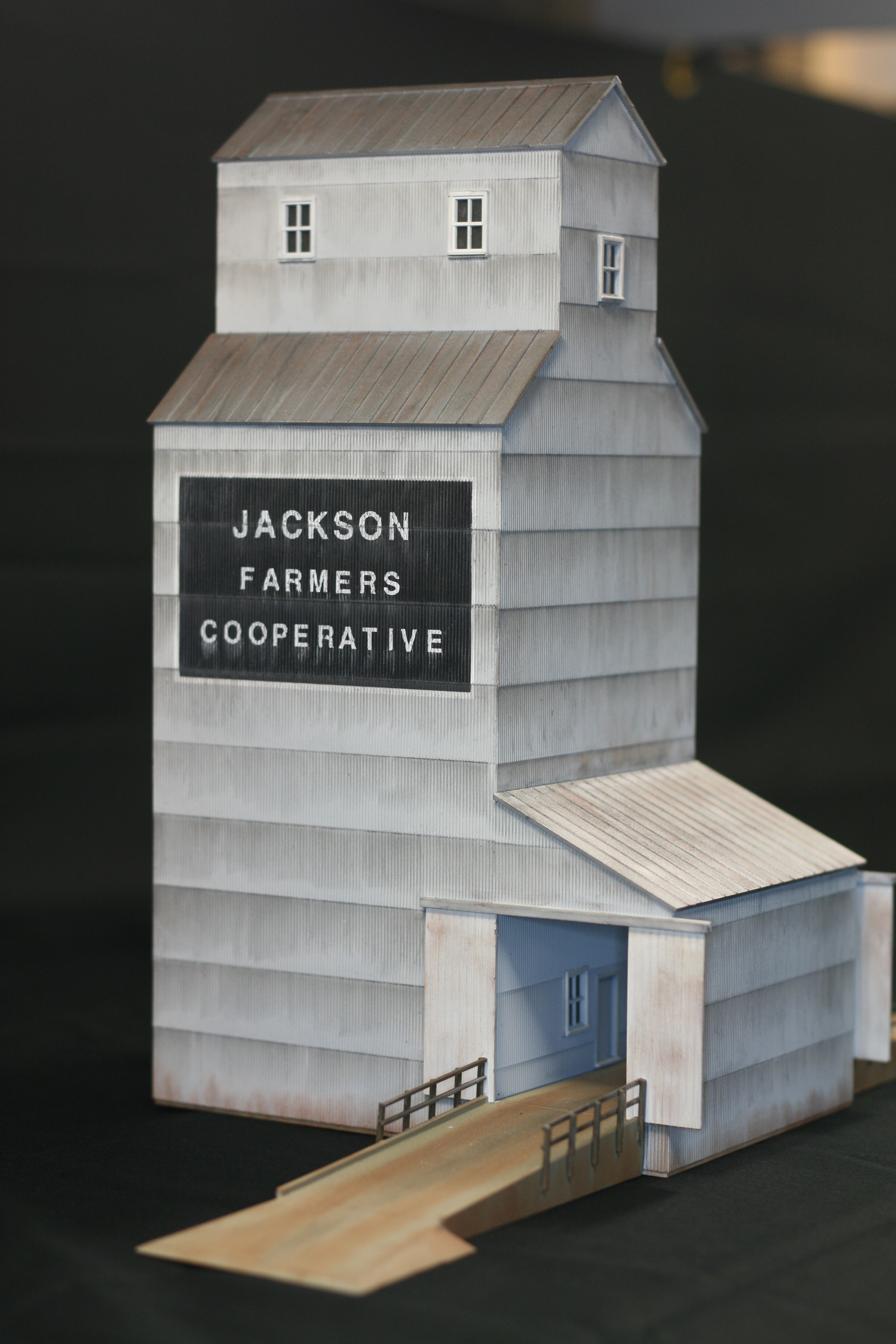
First up is the grain elevator for the town of Jackson, Minnesota. It is a Walther’s kit that I assembled with no modifications. It is the first time that I have used Pan Pastels for weathering. In the past I usually used weathering chalks for the main weathering. The Pan Pastels took a little more to get used to for weathing then chalks. With the chalk weathering you can gradually work up to what you want, with the Pan Pastels it goes on a little heavier. Thus care has to be used so as not to over do it. I am happy with the results and look forward to using them in the future.


Next up is the pier terminal. I have shown this before in a previous post but wanted to talk a little about it. What I quickly discovered with the upper deck is that everything is at eye level ( duh ) and thus interiors are going to be very important for this level. I Had to build a complete interior for the warehouse portion. This included all the buildings support structure, lighting and upstairs offices. The office in the upper corner is complete with desks, paperwork, a dock supervisor and secretary. It is also lit. I weathered this building with chalks.

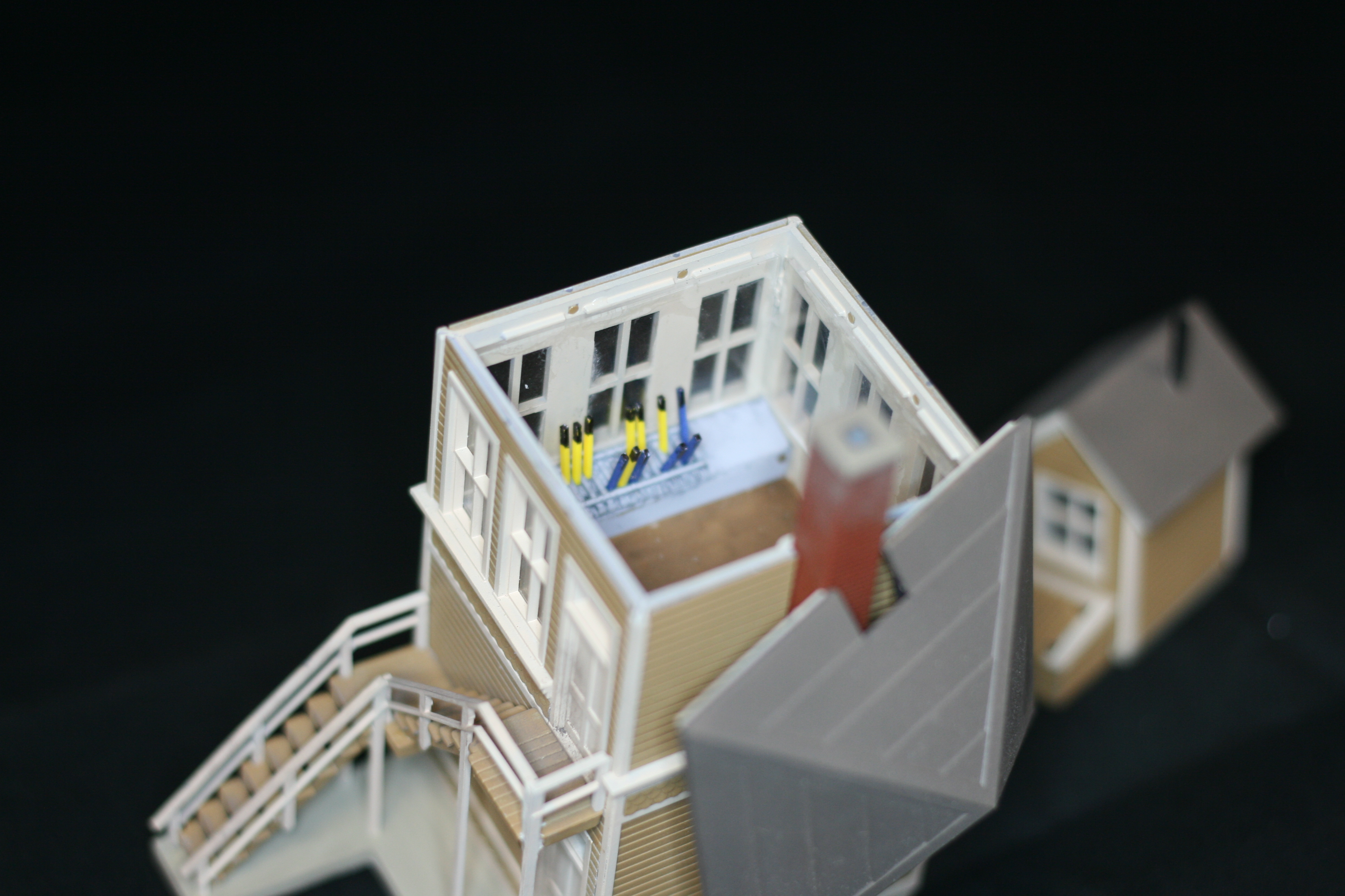

Next is the switch tower. Again it will be on the upper level and thus needed an interior. Since I was only lighting the upper floor that’s where I concentrated the detail. I added the switch levers and a desk area. For now I lightly weathered the building.

Last for now is the standard small town depot. Not much to say about it. Straight out of the box build. I will be replacing the train order boards with working ones from Tomar.
Since I’m unable to continue on the bench work due to the “car in the garage” , I thought that I would start laying track since I had already put down the plywood sub roadbed. No great revelations here folks, I’m pretty much old school when it comes to laying track. The roadbed is Midwest cork roadbed, nailed down. The track is then spiked to the roadbed, after the ballast is glued down I go back and pull the spikes on the track so the heads don’t show. This has worked very well for me in the past as when I tore down the old layout I was able to save about 90% of the track and switches by simply soaking the track with water and use a putty knife to lift it up.
I started with the staging yard as this really doesn’t take much planning if you know the length of it.

I drew the centerlines for the yard tracks and then laid the switches in place and marked their location. I began laying the cork from the switch locations and moved down the yard tracks. I like putting down the cork and laying track, for me it is relaxing and rewarding. It also tends to move very fast and I had the yard done in a relatively short time.


Again starting with the turnouts I put down the track.


I used the boxcar and the two passenger cars to check the trackwork as I progressed down the yard. By lightly putting your hand on the car and rolling down the track you can feel irregularities in the track and correct the problem. The same with the passenger cars, plus check the switch points as these will tend to pick the switch points if there is a problem.

I then moved to the upper deck, but first had to correct a problem with the level of the harbor. You know that old saying ” measure twice and cut once “, yeah, well I measured and did the math several times and it was still wrong. I cut spacers and raised the level and then moved on to figure out track location.


I had basically two industries planned for this leg of the benchwork, the Hullett unloader and the warehouse / dock scene. So it was just a matter of setting those to things in place and planning the track work from there. Not being a great railroad planner what I did was lay out the tracks that were necessary, the tracks for loading bay and under the unloader, and then adding the track and switches that made them work. I rearranged things several times until I had a layout that made sense, mentally doing switching moves and such. I may have to change 1 or 2 things after I power the section and can actually use the area, but I think it all makes sense.


As you can see I finished the second wall as far as I could go with available cut plywood. My daughters car broke down and showed up in my garage (wood working space ) and she is using my truck ( wood hauling vehicle ) until I get hers back on the road. As far as the wall system goes all I have left is 8 feet on the third wall.
My plan was to keeping working around the room on the bench work, because for continuity reasons it just seemed like the right way to do it. However since I had the supports leftover for the peninsula from the old layout I decided to push ahead with that part of the project.


The three pictures above are the wall spacing being measured out, the wooden case in the third was set at the layout edge to get a feel for the aisle width which is set at 42″. Once I was sure of all the measurements I got together all the pieces for the wall.

The center wall goes together much the same as the outer wall pieces using the spacers and although it is free standing will be tied into the two support columns. The real stability for the wall will come from the base cabinets which will be screwed to it on both sides. The uprights are 6″ wide with the same 12′ on center spacing. Again with the aid of the spacers work went very quickly and I had the wall together in a couple of nights.


Since they’ve shown up in previous posts I thought I talk about the ship models and structures for the harbor scene.
I scratch built both ships, the ore boat initially from the photo on the Sylvan website. Drawing it out was rather simple as the picture was from the front with the plimsoll marks visible on the bow. From there I made a ruler and could measure the rest of the ship. Using various images for deck structures I came up with a generic steam powered ore boat. I then drew it out full size and basically made a kit from .040 sheet styrene. The deck fittings are from Sea Port Models.

For the freighter, I Googled “Lakes Freighters” and found a Great Lakes museum website with photos of a wide variety of different ships. Working from general dimensions, I again drew plans and cut a kit. Again working with .040 styrene and Sea Port fittings I built the ship. The pulley blocks came from an old Revell sailing ship kit. Looking at the ship in the scene I think it sits high and will probably cut the hull down it get it riding a little lower in the water


The warehouse is a Walther’s kit (Walthers.com) from their Water Front series. I opened the dock doors and built an interior for the warehouse. I also added an office to the upper corner complete with a dock Foreman and assistant. The warehouse is also lit. I felt it was important as these structures are at eye level.

The Hullett unloader is also from Walthers. I am in the process of shortening it as it a little wide for the scene. Once that is done I will try and do it justice by weathering it. Once the scenery is finished and all the models are installed I have a variety of deck hands and dock workers that will complete the scenes.

I am still working on more backround buildings for the scene, but since I have not finalized the track plan for this area I am unsure as to what I’ll need.
This post goes hand in hand with the last post as lighting is being installed as the bench work is being built. The reason I didn’t talk about it then was because it would have been to much information for one post.
On the last layout I had experimented with several different types of lights for the lower deck. To answer the question, yes I played around with a variety of Christmas lights that everyone said would not work. I just figured they hadn’t done it right and I would be able to make it work. Yes, I know I’m an idiot.
So I figured on the new layout I was going to have to suck it up and spend the money on fluorescent strip lights. I planned on using T5 lights at about $10 a foot. This was going to get expensive as I figured to get around the layout was about 85 feet times 2, as I would need to light both decks. Then I “discovered” commercial string lights on Partylights.com, the type restaurants use over there patios. They are 50 foot strings that take standard light bulbs up to 25 watts. Not enough light if you’re using incandescent bulbs, but more then enough if using CFLs. I have since learned that the model railroad world knew about these, but no one told me about them.
But what to do with all the Christmas lights I had bought. Well the strings of C7 are strung over my deck for lighting, like the restaurants. And the ropes lights? I’m using those to light the aisles.

Once I installed the sub roadbed they give off enough light to light the aisles rather nicely. I will get a picture posted at a later date. I will be running a blue rope lights through the upper deck joists for night lighting.
As I had mentioned when assembling the upper deck I had to run the light string as I was assembling the bench work. One thing I failed to mention was that I originally spaced the studs on a 16″ center, but after buying the string lights I moved these to a 12″ on center spacing as the sockets are set every 24 inches. Fortunately this happened early enough in the process that it was easy to do.


I was pretty sure since CFL’s diffuse light rather well that even though they were set in every other bay there wouldn’t be very much light pooling. The moment of truth came when I had finished the bench work and installed all the bulbs. The result was perfect as the lighting is very even you as can see below.


After I finish all the bench work I be installing a valance around the layout and will be installing both the CFL’s and a string of blue rope lights, again for night lighting.