Cabinets in, bench work started.

I finished the first set of cabinets, installed and painted them. I won’t bore you with the details of construction as they follow standard base cabinetry construction. I painted them white as all the woodwork in the house is painted white. Also I had painted the cabinets in the work area white and wanted continuity between the two areas.

Base cabinets in place, painted and ready to go.

The space above them is the main staging yard, so I will be using these for storage of the engines and train cars. Shelves will be added soon, but the doors will be made after the rest of the cabinets are done as it is easier to do them all at the same time.

As the paint was drying I went back out to the garage ( also known as the woodworking shop ) and cut the “joists” for the upper and lower decks. I then made three drilling jigs for the three different size holes that I’m using for wire runs. Each joist has two 1″ holes, four – six 5/8′ holes and four 1/8′” holes. It may seem like a lot, but I figured it would be easier to keep like wires grouped together but separate. I also notched the upper deck joists for lower deck lighting.

View of lower deck joists set in place, note holes drilled for wire runs.

The picture above shows the joists set in place. The first step was too screw the end of joist to the stud and the outer edge to the cabinet. Again I started with the end joist to the left in the picture, mounted it, then using a spacing jig ( like the one used for the stud spacing ) moved down the line. I can’t stress, at least for me, how much of a time saver the spacing jig is. You’re not trying to measure the spacing for every joist. I then added a ” rim joist ” to the outer edge of the joists. I will then add a fascia to this after I start the scenery.

Lower deck joists mounted and installing rim joist.
Lower deck frame work done.

Once I finished the lower deck I painted the upper deck joists white for better light reflection, when dry I then installed them same as the lowers except instead of screwing them to the cabinet, I screwed them to the 3/4″ lip on the horizontal.

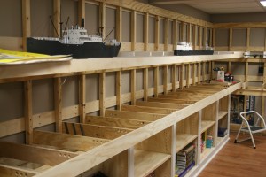
Upper deck Joists painted for light reflections.
Upper and lower deck framing done.

The plan was to keep moving around the room with bench work, but everything was working out as I had hoped so I wanted to add the sub roadbed to this area to see if there would be any sag or deflection. I cut the plywood for both decks and mounted it. The lower deck was solid, although with it sitting on the cabinets that was really no surprise. What brought about a sigh of relief was that the upper deck was also rock solid. No sagging and no deflection, even when I pounded on it.


The bench work construction has started!

My normal process when faced with a large project is mentally “build” the project, looking for problems that I could run to, possible better ways to do it and so forth. A model railroad is a undertaking that will take years ( unless it’s a project layout with a deadline, like a model publication project ).  Realizing this, I had to override my natural inclinations and press forward.

Wow, I’m glad I did.

The method I’m using is one of my own design, at least I haven’t seen it used any where else. I “developed” it on my last layout- some good did come out of it. I am building a mini stud wall with horizontal braces on the front and back of the vertical “studs”. For the horizontals against the wall I’m using 1×4’s cut from 3/4″ plywood. The studs are 2×2’s and the outer horizontals are 1×4’s cut from 1/2″ plywood.


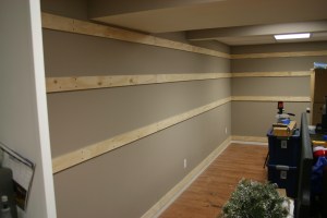
1. The horizontal braces in place. Top and Bottom are spacers, the bottom edge of the middle two set the deck heights.

The first step was the horizontal rails. The top and bottom rails are mounting point/ spacers for the studs. The bottom edge of the middle two set the height for the layout deck. I took great care in keeping these as perfectly level as possible, using both a 4 foot level and a laser level. They are screwed to the actual stud wall.

2. making sure the first 2x2 is perfectly vertical as this affects the rest.
2. making sure the first 2×2 is perfectly vertical as this affects the rest.

Then I added the first stud, again making sure that it was as perfectly vertical as I could get it because it’s alignment affects the rest of the studs. After it was screwed in place I used a pair of spacers made out of plywood and cut to the same length to mount the next. Once I got a rhythm down this went very fast.

4. Jig in place with the next 2x2 in place.
4. Jig in place with the next 2×2 in place.
5. Work moves pretty quickly not having to measure individual uprights.
6. First wall done.
6. First wall done.


With the studs in place I moved on to the outside rails. again top and bottom are spacers. The middle  two are mounted 3 1/2″ below the bottom of the inside rails, with the idea that the bench work deck pieces will slide in place. The outer edge of the bottom deck will be supported by base cabinets. For the top deck I added a 3/4″ piece to the rail to give added support and add a screw surface.

7. Outside horizontals going in place, again the top and bottom are spacers, while the top edge of the middle two support the bottom edge of the bench work.

The last picture shows the bench work pieces set in place. Once actually mounted they will be screwed to the stud and the top ones screwed to the rail, while the lower to the cabinets. Out of curiosity I didn’t fully hang on one, but did give it a large tug to test it’s strength. I was thrilled when there was virtually no vertical movement even though it was not screwed in place.

The next step is to build the base cabinets. This shouldn’t take to long and then on to actually building the bench work decks.

8. Test fitting the bench work.

Planning the layout – Realizations and Revalations

Even as I tearing down the old layout I was measuring the total space for the new layout. So as not to run into the same problems I ran into with the old one, I measured everything twice and started to draw it to a scale of 1″=1′. If I ran into anything that didn’t seem right I would go back and double check it again. Once I had it right, I took it to a copy shop that could do a large format copy and had a half dozen copies made.

I then marked off the space that was off limits, the stairway, access to the utility room and access to a storage closet. I also marked off space around what be the end of the peninsula and workbench area. I know, this would seem to be common sense, but it’s an area I “cheated” on before. I then started to sketch various ideas and when nothing worked out, that’s when I came to the realization that no matter how many track planning books, model railroad operations books or software apps, for some reason planning a railroad was beyond me. That’s not to say I don’t understand how they work, I can look at other drawn track plans and I get how the flow on those work. What goes where and why. I just couldn’t do it.

So now I had this beautiful drawing of my basement, but no idea on how to plan a model railroad for it. But as I was looking at the drawing of the space I realized that I had seen this space before with a very successful railroad in it. The answer was Jim Hediger’s Ohio Southern Railroad ( version two ). I found the article in MR and started comparing his space and mine, I found that they were very close. Now, I’m not copying the Ohio Southern, rather I’m using it as a template. I drew the footprint with just the mainline drawn in to make sure that things would work like I wanted it too.  I had a layout plan with mainline but without the individual towns, I figured I would work those out as I went along.

Then I had revelation number two. While looking through a back issue of MR, I came across an article about the Kirkland and DeKalb. The author had drawn an actual town and scaled it for a layout. It was an island layout with a staging yard on side and the town of Kirkland on the other. Looking at the town side of the layout I realized it would drop right into one side of the peninsula ( almost dimensionally perfect ). Tony Koester calls this a Layout Design Element. It’s then I realized that I could design the rest of the smaller towns in the same way, by finding pieces of other layout plans that could be adapted to my footprint

Now I had a working plan, now I could start construction.CN construction 4 024                                                          Drawing of the basement

The basement with the off limits area drawn in.
The basic layout drawn in
The peninsula with the Kirkland and DeKalb plan next to it


First I finished the train room

“First I finished the train room” or some variation of this always seems to lead an article in the model railroad press. Other times there might be a short paragraph of what was done. It makes it sound like the guy was sitting around on Saturday afternoon and thought “gee, I have my layout sketched out and I would like to start the bench work tomorrow . I guess I’ll go down and finish the train room.” Now before you say something, I realize that yes, it is a model railroad magazine article and not a home improvement article, but they make it sound like it’s nothing to get this done. It wasn’t till I started reading blogs that I found others were going through the same lengthy process it takes to make an environment that makes it a pleasure to build and operate a layout in.

Two people who have done a great job at chronicling this are Jason Shron, owner of Rapido trains ( kingstonsub.com ) and Alan who blogs about his LK&O Railroad ( lkorailroad.com ). Alan has done a beautiful job of writing about and recording in pictures what it takes to finish a basement. If your just starting out, I would recommend reading through his blog to see what to expect.

As I said in a previous post, I finished my layout room and then partially gutted it to rebuild it. When I first finished the basement I had wanted a dedicated shop as well as the train room. The support columns more or less divided the basement into thirds, so using those as a guide I ended up with a shop that was approximately 10 x 16 and a train room that was 19 x 21. I finished the shop with a dropped ceiling, second hand fluorescent lighting, sheet rock walls and berber carpeting. The train room got sheet rock, a stapled tile ceiling and what I thought were enough light fixtures. No flooring. While the shop was to roomy,  well lit and a pleasure to be in, the train room with the layout in it was dark, cramped and kind of sucked.

So I tore the layout down (  to the horror of my nephew ) and then took out the wall to the shop opening up a space that now measures out to approximately 19 x 31. I put in a dropped ceiling  throughout , added new drop in fluorescent lighting and put in a laminate wood flooring. I know the conventional wisdom is to go with carpeting as it easier on the feet, but my reasoning was that I’m pretty sloppy and it’s easier to clean up a hard surface than carpeting  ( plaster, paint, saw dust, etc. )

Side note: if your building a home, as we did, and you have the option of truss flooring or a joist flooring, go with the trusses, I wish I had . No support posts, no framing around pipes and duct work, just a nice flat ceiling and wide open space.

The remodel took about a 12 months, those bothersome work and family commitments getting in the way. When I finished, I stepped back and was amazed at the difference.

So now it’s finished, on to planning and construction.002001


What is the Continental Northern Ry

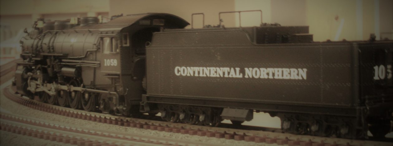
blog photos 007                                                          The Continental Northern Railroad as envisioned is a class 1 railroad set in the early 1950’s running from the upper Midwest to the Pacific Northwest ( picture the Great Northern or the Northern Pacific ) . My original plan, when I had the space, was to do a large layout with a series of separate scenes depicting different areas of the country to give a sense of moving across the country. Why? Because I had wanted to model the Midwest -you model what you know.   I also wanted to model a harbor scene. I love ships and ship modeling and had seen some great railroad/harbor scenes modeled in magazines. When we built our present home I finally had the space to attempt to model this. Unfortunately, the layout went horribly wrong. I tried to cram too much into too small of a space. I also ignored everything I had read about layout planning, too tight of radius, bench work that was way too deep, inclines that were too steep ( I should have mentioned I was trying to build it as double deck layout ) and on and on. After not looking at the layout for about six months I went downstairs, took a good look at it, had a heart to heart with myself and decided there was no saving it.  I had to tear it down and start over. I also took out a wall between the layout room and my shop increasing the space by about 50%. I now had the space to build a layout where I could hope to accomplish what I envisioned. The true turning point came when I realized that I could model just the eastern end of the railroad. I had overlooked the fact that just 120 miles north of Minneapolis ( my starting point of the railroad ) is the port of Duluth. I could have my Midwest railroad and a harbor scene without overreaching.  So, that is what I am modeling- an eastern subdivision of the Continental Northern from the Twin Cities to Duluth.

Hello and welcome

Hello and welcome.                                                                                                            I would like to thank you for visiting this site and hope you continue to stop by as I embark on my journey to build and model the Continental Northern railroad. If you had visited this site in the past (one of very few I suspect) and then found the site gone, I apologize. Life happens, work, family and other time commitments made it impossible to continue what I started at that time. I’m now on the other side of the things that would keep me from maintaining this site and progress on the railroad. Granted there will be times when other projects around the house or work will take precedence over the model railroad, there always is as everyone knows, I feel that I will always be able to offer a little insight about the railroad, progress or the modeling world whether I’m at home with no progress to report on or on the road for work with no ability to make progress on the railroad to report on.

As I become more adept at this I will be adding more content to the site, mainly my thoughts on the modeling world in general, pictures of my progress, the techniques which I am using for construction ( which I am very excited about ) , thoughts on planning a layout and projects on the workbench and the techniques used for these projects.

So again, hello and thank you for joining me.

Michael Bromander

Michael Bromander's Personal Website