October Update…

Welcome. If my last post was long overdue, then this one is almost inexcusable. For that I’m sorry. My wife and I have been traveling almost every other week for business and when we’re home it’s all about catch up. Working for a new company has been extremely time consuming, plus I have been overseeing a couple of build-outs for the company as they plan on moving into new work spaces.

After our last trip a couple of weeks ago, I thought that I would have plenty of time to accomplish some major work on the layout. We got home on a Friday night and when I woke up on Saturday, I could barely move. I had pulled a muscle or something in my back. Quite honestly it was probably lifting my wife’s suitcase as she seems to pack for any contingency (up to and including the Zombie Apocalypse), although she’s pretty sure it wasn’t because of that.

Being able to barely lift myself out of a chair, the thought of slinging a 4 X 8 sheet of plywood around was so out of the question. So sitting around feeling rather worthless because I couldn’t get anything done, I sat downstairs pondering what could be. That’s when my eye’s fell on a box of building structures that sat unstarted. If all I could do is sit, I might as well put that sitting time to use.

So that’s what this will be about, the kits that I was able to get built or at least started. And actually I think I got quite a bit done.

First up is a Blair Line Kit (blairline.com) of their Drive-in Theartre kit. Pretty basic kit, but it makes a great transition between the town of Jackson and the surrounding  countryside as these were always on the outskirts of towns. I love the way it turned out and can’t wait for the surrounding scenery base is place so it can be placed.

Blair Line drive-in theatre outside the town of Jackson.

Second up was another Blair line kit. It’s their Fertilizer plant ( or dealer depending on what part of the country you hail from ). It is a laser cut / peel and stick kit. The precision of which the parts fit is outstanding. I was a little hesitant about the stick on parts but the adhesive is surprisingly strong. Loved it so much I have been checking out the rest of their line. Once I start actually placing the structures and scenery there will be a lot of details added.


Blair Line fertilizer plant for Jackson. My first laser cut / peel and stick kit. I loved the precision and ease of this kit.


The other end of the plant.
Alternate view of the fertilizer dealer.

It still needs signage and weathering, but I love the kit.

Next was a Walther’s kit (walthers.com). I had picked up Al’s Victory Service, although the kit is now made with a different name. I couldn’t build it as it is made because the space wasn’t large enough. I had too shorten it from a 2 bay service garage to a 1 bay station. Also since the customer area was going to be more noticeable then the service bay, I had to dress it up a bit. First was the floor, I decided that the floor should be that ambiguous tile floor. And then I added a couple of chairs and a table, as well as a counter. I will also add lights and people as well as weathering.

Beginnings of the black and white tile floor for the gas station.
Masking all in place.
How it looks painted and with the gas station in place. Not perfect, but it adds a lot to the finished kit.
Gas station in place. General location but will be adjusted as I get the lot in place.

Another quick kit that just had to be in a small town was Walther’s Vintage Dairy Queen. As a child I remember the trips to visit my grandparents in northern Minnesota. My father was a Dairy Queen fiend and we would always stop at one in one of the small towns along the way. So it only fits that there had to be one in Jackson. Like I said, it is a quick build but still has a lot of detail for a small kit. I will add lights and people but weathering will be light as they always seemed to be well kept.

Walther's vintage Dairy Queen.
Walther’s vintage Dairy Queen.

The last kit that I’m working on is from JL Innovative Design (jlinnovative.com). The kit is Wilbur Shaw’s Speed Shop. I picked it up at a train show (actually, I picked up several of their gas station kits, I’m not sure why so many).  Mostly done, but it will need a bunch of detail, mainly the service area as it is rather big. I will probably pick up their service station detail set. This kit will not be in Jackson but rather at the outskirts of New Brighton.

Wilbur Shaw's speed shop under construction.
Wilbur Shaw’s speed shop under construction.

The sign holder jutting off the end was supposed to be made of balsa and card stock, but the combination seemed kind of flimsy, so I made a styrene one to hold the signage.

And one last thing. I received my order of data only boxcars. Still waiting on the custom decals for the Northern Continental road name. I will finally have some home road boxcars.

The next big project. Waiting for custom decals.

Obviously I will need more then a dozen boxcars for the home road, but it’s a start.

I’m not sure what the weeks ahead hold, but I’m sure that soon I will be able to get started on the helix and other projects on the actual benchwork. Please stay tuned.

And again, thanks for stopping by even though progress has been slow.

Happy Railroading…
 

Long Overdue…

Yes I know, this post is long overdue for a couple of reasons. First, I appreciate everyone who has stopped by even though there wasn’t anything new for the last month. It’s not for lack of trying, and I hate to keep using the excuse that life happens ( even though it does ). On my last post I said that I should have something to report on within a week or so, and I truly thought I would, but things didn’t go as planned. So here it is, but life happens.

I could have also titled this post ( and happily so ) ” Benchwork completed “. Yes that’s right I finally finished the base for the helix, which technically means all basic benchwork is in place.

Other than everything that has been going on, I think the biggest hang up for me has been the fact that I had to cut open the wall to the utility room in order to get enough room for the helix to fit. I realized this as I stared at the wall and had a hard time imaging chopping into it. I did finally overcome the reluctance and pushed forward.

When we built the house in ’97 I noticed a trend in higher end homes and decided that I wanted a “wired” home. Unfortunately the builder didn’t have a clue what I was talking about. He was however willing to let me do the work myself after his crew left for the day. So I drilled holes, installed the boxes and pulled cables with the help of the kids. Multiple coax cables for antenna and cable, multiple phone lines, data cable for the LAN and whole house stereo. Even the building inspector kind of looked at me funny, but since it was all low voltage  lines he just shook his head and gave it a pass. What has this got to do with opening up the wall you might ask. Well as it turns out some of this terminated on the wall in the utility room I was about to tear out. So first up was to relocate this to a different wall, and after a couple of days I was ready.

And then it was time. I marked the section of wall that had to come out for the helix to tuck into the utility space. After it was marked and I re-measured to make sure that there would there was enough clearance to get the beast into place, I cut out the sheetrock and wall studs that needed to go. After that I installed blocking between the studs to protect the sheetrock from breaking and to give me a base for that day when I would have to repair the wall.

Wall marked for cutting with the ledger already installed.
Hole cut in the wall with blocking installed.

Before building the helix base I had to disassemble some of the adjoining benchwork. I had mentioned this before as I was moving the berm scene over slightly and had to recut some of the joists for that benchwork before I could complete the helix base. Once done the benchwork for the helix went together rather quickly. I wish I had not put this off as I would be much farther ahead today. Oh  well. Below is a photo of the benchwork with a cardboard template laid in place. Even though I tend to be able to visualize things in 3D that I have drawn out, the size of the thing still took me a little by surprise.

Helix benchwork installed with the helix template in place.

Also, below are a couple of photos of the reworked berm scene. As you can see from the picture looking down the tracks towards the helix the mains are going to have to curve slightly to the left to avoid the helix, but the third track that is the staging/return loop will run right in to place. It’s going to take some creative scenery/building placement to hide the track leaving the main and going under the helix. Again, oh well, no said it all was going to be simple.

The benchwork adjusted and bridge scene set in place.
Birds eye view of the bridge scene.
View down the tracks to the bridge scene with the template in place for the diverging route to the return loop.

You will also note the diverging route that will cut through the backdrop, again something that is going to need a little creativity to hide.

Next up is laying the plywood base for the helix. I plan on covering the whole base with 3/4″ plywood, probably not necessary, but it will make a more secure base. After that will be running the return loop and getting it operational and after that… the helix itself. I hope things will progress more quickly then they have, but I can’t promise anything.  We are quickly running out of summer and there are things that have to be done before the weather turns. I will make a point of not letting some much time elapse between posts though.

Until then, Happy Railroading…


Early July update…

Just got back from another week long business trip, but during the week I was home before this trip I was able to get a couple of things done. I just didn’t have time to post anything.

Heading south from Jackson you come around the bottom leg of the peninsula into the  city berm scene I had talked about before. Below is a photo that I posted before, it’s of the scene as originally conceived.

Head on view of the bridge/berm scene.

It’s kind of hard to see from this angle but I had intended to have a double track bridge with a single track bridge right behind it. As I actually started working towards this scene I found out that I didn’t have enough room to get the rear track switched off the main and head onto the rear bridge. Looking over the situation I found I could get the track separated far enough if I – A: moved the whole scene over about 8″ and – B: changed the double and single bridges into a single triple track bridge. I was able to modify the girder portion of the bridge into a triple track bridge as the Walthers kit is made for this modification. However, having already built the abutments, modifying them wasn’t as easy. In fact, to say I butchered them would be extremely kind.

So off to the LHS to get a couple of new bridges. For those who care, my hobby shop of choice in the Minneapolis/St. Paul area is Becker’s Model Railroad supply in New Brighton. He had one kit in stock and ordered the second which I had in a couple of days. In case you’re wondering I needed two kits because they build into a double track bridge, if you want three tracks you need two kits.

One of the things I found is that when you build this kit as instructed for a triple track bridge you will end up with about a 1/2″ gap between the girder portion of the bridge and the actual bridge abutment, which works out to about 4 scale feet. The gap is extremely noticeable and looks like crap. So I took some time and studied the model to figure out how to modify it to eliminate the gap and have the abutment look symmetrical. I should note that I had to build the abutment first as it sets the width of the subroadbed.

Below is how I modified and built the abutments.

First I modified the base of the abutment which is also the sidewalk. I marked where I would cut the sidewalk section. In the photos below I highlighted these with arrows.

where the splices in the base plate were made. In addition to joining for the third bridge deck, I had to shorten by half an inch.

After I cut and joined these I  began the modification of the actual abutment section. I started with the pillar section of the bridge.

The placement of the splice cuts for the bridge abutment.

The photo above shows where I cut the pillar section. One of the things that the instruction wants you to do is to cut the double pillar( the center one on the lower pillar section ) but I figured if I cut through smaller cross section next to the double pillar I would have a less noticeable seam to fill and hide. Below is a photo with the cuts made, but before assembly.

Base cut and glued together and the abutment ready to be glued.

Once I started to glue the pillars together, I also started to glue the backings on to add strength but I made sure that I staggered the joints so that no two joints were on top of each other.

The joints for the rear of the abutment, cuts are offset to add strength to the front of the abutment.

Once the pillar section was done I glued the works together, filled and sanded the joints.

The bridge abutment glued together and joints filled.

Though I kept checking as I was assembling the abutment, once I finished I put the girder section in place and was happy with the result as there was very little gap when in place.

Bridge deck fitted to the bridge abutment.
Bridge abutment primed and waiting for the finish color.

After I finished the bridge abutment I was able to cut the subroadbed and put the works in place. I was then able to lay the cork roadbed in place.

Roadbed laid up to the bridge.

In the photo above you can see a track that is heading to nowhere. The track to nowhere and the rear track on the bridge are for a return loop that will be underneath the helix and needs to be in place and operating before the helix goes up. In the original plan the area I’m using as a return loop is actually a set of staging tracks that feed into the yard. I reversed the direction so that I can set up a portion of the layout with continuous running. Trains can reverse here, run around the peninsula, up the helix and again around the upper portion of the peninsula and then into a reverse loop on the upper level. When I picked this plan, continuous running was the one thing I felt it lacked. I was happy when I figured out how to do this as I like to sometimes watch trains just run. Also I can orbit a train as I switch towns and have to clear the mainline as the other train comes through.

Below is a photo of how the scene will look when finished.

Low angle concept shot of what I want the finished scene to look like. Obviously there will have to be some modification of the bench work that is in the way.
Birds eye view of where this scene is headed.

As you can see in the photos I will now have to do some modification of the bench work structure as it is the way of everything. The up side is that I now have more room for structures in the background which will greatly add to the depth of the scene.

I know that I have been putting it off for what seems like forever, but I have some open time coming up. Which means that I will have the base of the helix done probably within the next week or two. This is truly important as it is not only the base for the helix but also the tracks leading into the yard at New Brighton.

Stay tuned, and Happy Railroading…


The town of Jackson…PT2

I have finalized the track layout for the town of Jackson and having done so, laid the roadbed. For those who are wondering, no I’m not avoiding the helix base, I just haven’t had any large blocks of time. But in an effort to keep moving forward, I have been using the little snippets of time that I have had to keep moving forward.

I was able to keep the original track plan pretty much intact. The only major change to the plan was that I had to eliminate one of the crossovers between the southbound main and the rear siding. Other then that it more a matter of shortening some of the distances between things up a little. As I had mentioned last time some of this was accomplished by flipping turnouts around.

While planning the track arrangement I had photocopied the needed turnouts so that I could use them in the actual planning of the track arrangement. In the past I would have one of each turnout on hand and I would just mark there location and then move them to the next spot. Because I wanted to make sure everything was working right I used the photocopies and was then sure that it all flowed well.  I then decided that I would glue them in place so that when laying the cork roadbed I would have an exact guide as to where to lay it. I have seen this done on larger club layouts ( and I’m sure that a lot of other people have done this on home layouts ) but I have not done this in the past and I’m wondering why I haven’t. Sometimes things take awhile to make it all the way to the top. It made everything so much easier and I will continue to do this for the rest of the layout.

One thing I did before I glued the photocopies down was to mark where the holes needed to be drilled for the linkage from the Tortoise switch machine. I then used the drilling template from Tortoise and drilled the linkage hole and the mounting holes. Normally the mounting holes would be drilled from the bottom and then they would only be drilled partially into the wood for the screws, but it is easier to drill all the way through the plywood from the top. The holes are small and will be covered with scenery ( actually they will probably be covered with ballast ) so I figured it really doesn’t matter which side as long as they are there.

Below is a photo progression of the work:

Predrilling all the switch motor holes.
Switch templates glued in place.
Start of the roadbed for the town of Jackson working north to south.
Half ways through the town.
Except for two of the sidings, one on the north end ( in the foreground ) and one on the south end ( background on the right ) roadbed is down.
Looking north through the town.

As you can see in the pictures I also laid cork down for known structure locations, these being the depot / freight house and the elevator / feed mill. I also put down cork where the main street intersects the railroad tracks. I stub ended the roadbed for the two rear siding tracks as I have yet to figure out what exactly will be back there. The short list right now is a manufacturing plant, an oil dealership, a mill and a fertilizer plant. Stay tuned.

A couple of photos with some of the buildings in place:

Closer view of the depot / elevator scenes.
Alternate view of the elevator / feed mil scene.

I should have some time after the 4th and hope to have the helix base in place, we’ll see.

Until then, Happy railroading…

End Of May Update…

End of May update… also know as ” nothing has really gotten done”. New job, new challenges. Since my last post I have been out of town for two of the last three weeks. The one week I was home I was fully engaged in work issues and unfortunately this is the way it will be until things are straightened out with the company we are now working for.

I have had a chance to get a few things done. In my last post I had talked about starting the planning for the town of Jackson. What was pictured was some general planning , but I have been working on specific planning and have about 50% of the town laid out and finalized. I should have the whole thing done in the next week or so.

I also have been working on some background buildings for the port of Duluth harbor area. I have been using Design Preservation Models wall sections to build some of the buildings and this is working out well. When I have something to report on I will let you know.

The other thing that is happening is the lower level remodel is done and the furniture is out of the basement. If I have a chance, I might have a chance to start the base for the helix, which would finish up the basic benchwork. If this happens, trust me, you will be the first to know.

Keep your fingers crossed.

Until then, Happy Railroading…

The town of Jackson…pt.1

Oh yes, the town of Jackson. As I mentioned in my last post the town of Jackson has turned into it’s own special little hell. And of course it is all my own fault. As originally planned the layout was longer down the length of the peninsula and the town of Jackson ( Kirkland in the original plan from Model Railroader ) almost dropped right onto the layout. And then I screwed up.

First, as I mentioned before in an attempt keep from buying things I didn’t need I started building model ships. Once built, I needed some place to put them, so I put up a wall of shelves. It’s really nice to have someplace to display them and I have received many compliments on them. However they stick out 12″ and the layout had to be shortened. No problem it’s only a foot. Then as the peninsula was being built and I was moving around what would be the end of the peninsula I figured I should have more then the 3 feet I had figured for an aisle, so I expanded it to about 4 1/2 feet. This gave me a comfortable aisle to move things around without hitting the layout or the ships on the shelves. As the peninsula was about a foot short of the original Kirkland plan, plus the foot for the shelves and now another 1 1/2 foot, I was now 3 1/2 feet short.

Second, as I was building the end of the peninsula I shortened up the transition where the table flairs out for the rounded end of the peninsula.

View down the outside leg of peninsula. The town of Jackson is in the planning stages.

As you can see in the above picture you will note that the subroadbed pushes out almost to the edge of the benchwork. You can bet that as I am laying track, that I going to be sure that it is as perfect as I can get it. A derailment here would be catastrophic to say the least. But as of right now I believe that I can live with it, as the alternative is to decrease the radius of the turn and I am unwilling to do that. It’s one of the major compromises I made on the last layout and I always regretted it. A possibility here is to superelevate the turn.

Planning the town itself has become something of a challenge as I try to get everything into it that I liked from the plan. I realize that some things  might have to be left out or shortened. But I’m trying to keep the flavor of the plan. I have found that in some places of the plan that by flipping a turnout around, meaning flipping the straight thru part with the diverging route, I can pick up space as you don’t need to have a straight section to avert an s-curve.

I will continue to plug away at it until I have a workable track plan that I can live with and don’t feel as I’ve compromised. Below is the start of the planning.

Planning the track arrangement for Jackson.
Closer view of the beginnings of the track planning for Jackson.

As you will note from the above pictures, I made it over to the storage locker for some of the needed buildings. I thought I had the box with the throttles in it, but I didn’t. I guess another trip is in order.

Until next time, Happy Railroading…


Early May update…

I know “Early May update” is a little ambiguous, but I was unsure as how to title this post as I have accomplished two different things.

First, when I was planning the layout I knew I would be building a helix to connect the decks. It was the how that I wasn’t sure of. There are about as many ways to build one as there are people who build them, probably no single one is any more “right ” then any other. I just wasn’t sure how I was going to tackle it. Because you can’t obviously cut a whole helix out of a single piece of plywood, you are going to have to join the individual pieces together. Which in turn means that you are going to have to allow for clearance for splice plates if used on the bottom of  individual pieces or come up with a creative way to join the pieces together where you don’t have to worry about clearance issues.

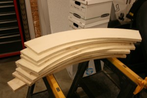
I decided to go with the latter. First was to try and figure the most efficient use of a piece of plywood. You can’t get a full turn out of a 4′ x 8′ sheet, but you can get two half circles out of one but with a tremendous amount of waste. Same goes for 1/4 turns. But I did figure that if I broke the circle into sixths ( a 60 degree arc ) I might be able to efficiently use a full sheet of plywood. Second was how to join the pieces together. What I came up with was to use 3/8″ plywood. I would take the 6 pieces and lay them out in a circle and then laminate them to 6 more pieces offset by half( a joint every 30 degrees ).

Then the problem was cutting all the pieces out and getting them to align right. I figures I could cut a master out and then use it to make the pieces using it and a pattern bit in my router table, but the thought of trying to get a ” perfect” master was a bit beyond my abilities. Turns out I didn’t have to . It occurred to me that my brother owns a metal cutting shop that uses high pressure water, computer controlled cutting machines. I asked if he could do this for me and gave him the dimension that I needed, he plugged them into the computer and in no time I had a the master I wanted cut out of 1/4″ aluminum.

Now I wish that I could tell you that I was cutting the pieces for the helix, but I still have that issue of the train room being used for storage while we wait for the carpet install. What I am doing though is working on the subroadbed leading up to the helix as I need to set the entry height of the helix loops.

I bought a half sheet ( 4’x 4′ ) of 3/4″ plywood for the curves around the end of the peninsula and using the master, traced a bunch of curved section on it to try and see how many I could expect to get out of a full sheet. I was hoping to get 12 pieces as this would be enough for a full circle ( when using the 3/8″ plywood ), as it turned out I got 7 pieces out of the half sheet which means I can comfortably get 14 and possibly 15 out of a full sheet. YAY!  Below are a series of photos that shows how it was done.

Curved subroadbed laid out for cutting.
The 1/4" aluminum pattern.
The 1/4″ aluminum pattern.
The blanks cut and ready for the router table.
The first blank ready to go through the router.
The first curved section cut and routed.
The set, though not lined up, all are perfect duplicates of the pattern.

Since I already had the plywood base in for the town of Jackson, I worked up and down from there. Jackson is 3/4″ above 0, so I worked down from there to my 0 height. Coming out of Jackson is the end of the peninsula. The half curve there is a 2″ rise which matches the rise in the helix. If a train has a problem here, it won’t make it up the helix, better to know where you can see the train then when it’s in the helix and you can’t see it. Below are photos of the curves installed, you will also see that I got the backdrops painted.

the first curve in place. The incline matches that of what the helix will be.
View down the inside leg of the peninsula.
View down the outside leg of peninsula. The town of Jackson is in the planning stages.
View at the end of the peninsula.
The bottom leg of the peninsula, this is where the climb to the helix starts.

As you can see I also started planning the track arrangement for Jackson, but as it turns out it is it’s  own special hell and worthy of it’s own post.

Until them, Happy railroading…


Late April update…

Since my last post ( well not actually my last post which was about my 1 year anniversary, but the one before that ) I spent time getting ready for a business trip and  then was in New York for 7 days. Once we got back it was catching up on work around the house, both business and personal. When I had a chance to get downstairs  I sat there and lamented the fact that I couldn’t move ahead on the layout  until our little remodeling project was finished.

Let me explain, the “remodel” isn’t anything more then paint ( finished ) and new carpet on the lower level. The reason I can’t move forward is that when this happens all the furniture from the lower level ( family room and bedroom  ) has to go somewhere. And that somewhere is the “basement”, also know as the train room.

When we finally got around to ordering carpet I found out that the install wouldn’t be until mid May. Not wanting to sit around and stare at the layout without making progress, I decided that I had to do something. So… I decided to break my rule of working in a linear fashion ( ie. completing the bench work before moving ahead with other things ) and move ahead. Technically anyone who has been following this site will note that I had already broken this rule because I had laid track in both the staging yard and part of the Duluth harbor area.

My first thought was to wire in the feeder wires for the staging yard, but this seemed a little to tedious. Also I haven’t had the chance to get over to the storage locker to retrieve the throttles.

I then turned towards putting the subroadbed in place leading to the helix. This will have to be done before I can start the actual helix as it will set the height for the entry into the helix’s first turn. This also meant that I should put the backdrop panels into place on the lower level. And thus I had a plan. So starting from 0 ( the level of the staging yard and New Brighton Yard ) I worked around the peninsula counter clockwise. First stop the town of Jackson.

There will be a 3/4″ rise at Jackson, so I installed risers along this section of the peninsula for the towns base. Fairly simple, a ripped 1″ wide strips of plywood and screwed them to the joists.

3/4" risers for the town of Jackson.
3/4″ risers for the town of Jackson.
View down the peninsula with the risers in place for the town of Jackson.

After the risers were in place I added in the backdrop along this section.

Overview of risers in place for the town of Jackson. Backdrop in place.

And then I couldn’t help myself I had to put the subroadbed in place for Jackson so that I could get a sense of the space I had for the town.

Backdrop and subroadbed in place for Jackson.

And now because I had the base for the town in place, I wanted to start laying out the town, but I stopped myself, because then I would want to layout the track plan for the town and then start laying track and then… You know – if you give a mouse a cookie.

So I continued and finished the backdrop around the lower level. The only areas that I didn’t do are those that will be next to the helix. Until it’s in place I not sure of the backdrops final location.

View down on side of the peninsula with the backdrop in place.
View down the other side of the peninsula with the backdrop in place. Template for the subroadbed for the curve around the end of the peninsula is in place.
Overview of the backdrop in place around the lower level.

After finishing the backdrop I was able to start planning the town of Jackson. However this does mean a trip to the storage locker because some of the buildings that will populate Jackson are packed away in boxes there. Well I suppose I can pickup the throttles at the same time.

Beginning of the town planning for Jackson.
Alternate of the beginnings of the town of Jackson.

Until next time, Happy Railroading..


1 year old today…

This will be quick as I really don’t have anything to report on. The reason for this post is that this site is one year old today.

By the numbers I’m happy with what I have (just over 2000 visits ) however, the number of comments are a little on the light side. If you stop by don’t be afraid to say something. Positive comments are always welcome, but I’m a big boy and can handle a little criticism. Of coarse when you start something like this you hope for tons of people to stop by, but I imagine as I get further along and have more interesting things to talk about and show, the numbers will pick up. I mean after all, how many times do you want to hear about bench work construction and cabinets.

Having said that though, it was important for me to get them done as I can get easily distracted and start working on a myriad of other things. I quite honestly have had to stop myself from going “great, now I have some benchwork done, I should lay some track. And then, well the track is in I should add scenery.” And on and on and on…

Soon I have eight feet of layout detailed with scenery, but really no where to run a train. Been there, done that. So then you finish another eight feet, but still can only run something back and forth. Soon the whole project looks unobtainable, as I think I have to have everything completed to this degree. Though for you out there my progression is a little boring, but for me it has been for the best. So please hang in there, things will become more interesting and I believe it will happen soon.

And again, thanks for stopping by, I do truly appreciate it.

And to me, Happy Anniversary.

Until later, Happy Railroading…

Wiring started…

I started the wiring for the DCC system. As I said in my last post I am temporarily unable to start the base for the helix because of a minor remodeling project.

I started by wiring the 44 pin connectors for the Digitrax (www.digitrax.com ) PM42 Quad Power Manager.  I wired up four of them, why might you ask. Well, I am going to have 8 power subdistricts, so I will have 2 PM42’s. But when I built the tower for the DCC equipment I put in spaces for four slots. I had 1 good connector and picked up a pack of 3 additional connectors ( that’s the way they are sold, why, you would have to ask Digitrax ). Since I had 4 on hand I decided to wire up all 4, my reasoning being either because of future expansion ( I can’t imagine gaining enough space to need more power subdistricts ) or because if one the connectors failed, I could just move the circuit board over to a new connector.

I started by building a jig to hold the connectors in a stable cradle while I wired them up and soldered them. I used 14 gauge wire except for the power for the boards. In order to get the 14 gauge wire to fit in the oval slots on the connector I had pound the round wire into a shape that would pass through the slot. It took a few attempts to get them right, but once I figured out how much it took to get them to fit it was pretty easy.

Below are pictures of the finished connectors wired up, on the long bare wires I applied a brush on insulator.

The 44 pin connectors wired up.
Close up view of the 44 pin connectors wired up.
Liquid insulation applied to the long bare sections of wire. Connectors are ready to be installed.

Next was to install them into the DCC tower. Because of the way I built the cabinets, I had about 8 inches to work in. For reference a standard screw driver is about 9 inches long, so I had to get my two hands and a stubby screw driver into this space and attach the connectors while wrestling with stiff 14 gauge wire . Oh yeah, a lot of fun. It took a bit, but I got it done.

View of the connectors installed. A rather tight space.

I then ran the wires for the first PM42 and hooked them up to the barrier strips. Below are pictures of the electronics cabinet with the wiring in place.

The first install into the electronics cabinet. The first row of barrier strips are for the 4 subdistricts on the lower deck.
Overview of the electronics cabinet next to the DCC cabinet.

As you can see in the above photos I also ran the first two sets of buss wires and have them hooked up to the top two barrier strips. The first (top ) strip is for the staging yard, the next one down is for the New Brighton yard. The lower two are for signaled districts and that is why there are larger strips as each separate signaled section needs it’s own terminal.

It’s while I was running the first two sets of buss wires that I truly appreciated taking the time to drill all the holes for the wire runs. Running the wires went very quickly and neatly. Below is a picture of the buss wires run under what will be the New Brighton yard. The two wires ( red and black ) run in the separate holes are for that yard. The separation should make it easy to hook up the feeder wires. The pair running above them are for the staging yard and will separate into separate runs once they are under the staging yard.

Buss wiring run on the lower deck. The upper pair are for the first subdistrict, while the lower wires are for the second , ready for the feeder wires to be attached.

Okay… so I had the command station and booster hooked up, the PM42’s wired in and buss wires run, so I figured why not give it a try. So I run a pair of jumper wires from the staging yard buss to one of the yard tracks ( I had not run the feeder wires in yet ) and as I was grabbing a locomotive to try I realized I DID NOT HAVE A THROTTLE! Let me explain: when I was finishing the basement for the layout, I had to move all the boxes with the railroad stuff into our storage locker. Most of it is still there except for stuff that I had room for in the cabinets. Unfortunately the throttles fall into the former group. So I had everything in place and no way to try it. With an upcoming business trip I won’t be able to retrieve the throttle to try it out for about a week. I guess that’s life.

Until that happens, Happy Railroading…


Michael Bromander's Personal Website