Workbench Wednesday #4…

In this edition of workbench Wednesday I will continue on with the grain complex.

Having finished basic construction it was off to the spray both. Not a easy task as my booth is two feet wide by two feet deep and the complex is just under 30″ assembled. The walls are all flat white. My first pass through with the roof was a dull silver, however they really stood out. I didn’t think any amount of weathering was going to change that. So I repainted them a light grey.

In the pictures the walls and the roofs look a lot closer in color than they really are.

complex painted, awaiting weathering.
Alternate view.

Side note: after painting and before weathering I added the shingle roof to the office.

I started to weather the building using Pan Pastels (panpastel.com). I have two sets, one is weathering earth tones (rust, browns, white) and the other has black and grey tones. Really like the thought of them and all the demos I have seen make it look easy. However, it requires a lighter hand than I seem to be able to master. So I went back to my weathering chalks. I’m use to them and can control them better. I did use the pastels when doing the rust color and I think it turned out well. Baby steps I suppose.

Anyways, this is how the complex stands now.
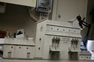
Sorry about the angle, complex weathered.
Main building with dust collectors and grain loading pipes weathered.

I also did the grain bin. I used a technique that I had used on a sheet metal sided grain elevator to highlight the banding on the bin. Not one hundred percent sure I like the look. I’ll let it sit a bit and decide if I still like it before permanently installing it.

Grain bin finished and weathered.

And this is the complex sitting in it’s new home.

The complex set in place.
Looking south down the mainline at the complex.

I still have the large transfer pipe to weather and I have to add the window “glass”, but for now it is basically done.

Since I have the helix now to work on, I’ll walk away from it now before deciding if it needs a little more and what fine details to add.

I will get you an update on the helix soon. Till then…
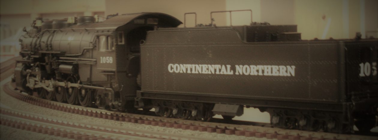
 

Finally, The Helix…

I have finally taken the first steps towards starting the helix. It is long overdue. This past weekend I had a large block of time.  And since it was still warm enough in the garage without heating it I picked up the plywood and started cutting.

As I had mentioned before (it’s been awhile, May 2015) I have a aluminum pattern that I had made for the curves. Using the pattern I trace out the curve section on the plywood (I can get 16 curved sections on a 4 x 8 piece of plywood). I then rough cut out the pieces. Then again using the metal pattern screwed to the rough cut pieces I run them threw the router using a pattern bit. I had detailed this along with pictures in the May 2015 post if you want a better idea of how it works.

I need 12 curved sections per loop. Six would complete one loop if I were using 3/4″ plywood. However than you would have to join the pieces together without creating a clearance problem. My solution was to use 3/8″ plywood and laminate the pieces together offsetting the joints to crate a 3/4″ thick ring that would have nothing below to cause clearance issues.

The stack ready to go.

All loop pieces ready to go. Also 4 sections for the entrance and exit from the helix.

As noted there are also four pieces (bottom of stack) that I cut with straight sections leading into and out of the helix.

My plan is to assemble them away from the layout one loop at a time. I will glue, clamp and screw them together.  Then I will add that loop to the layout, lay and wire the track. I will then run a test train through it before going on to the next loop. After the first loop works I will repeat the process.

The thought of trying to mark the locations for screws and the center line of the track kind of boggled my mind. A little thought and my next great idea. Back out to the garage and in no time I made a couple of marking gauges.

They ride along the edge of the roadbed and have holes in them for a pencil to mark screw and track locations. One is for the inside of the curve and the other for the outside.

Tried one out and this is what it looks like.

I should have the first loop completed and installed this week. Will keep you updated. I will also have an update on the grain complex for you on Wednesday.

Till then, Happy Modelling…

Workbench Wednesday #3…

Welcome back to Workbench Wednesday #3. Got the order from Walthers (walthers.com) and should have enough to complete the project. So let’s jump right in.

Finished the long front wall of the main building first and then the upper wall and cupola.

Nearing completion.
Upper walls in place. Now just the roof.

Before adding the roof I wanted to complete all pieces of the overall structure. Honestly, I wasn’t looking forward to the roof as all subassemblies except the office had steel roofing. If you have ever done Evergreen steel roofing you know that all the individual raised seems of the roof have to be glued in piece by piece.

Next up was the office. Basically kitted this one. Laid out and cut the walls and a center support. Cut out doors and windows and then assembled.

Office walls cut out and ready for assembly.
Corner bracing added. Decided to add a center piece for support.
Office assembled.

Did add the roof to the office right away as it would be shingled.

Office complete, not planned, but ended up with some nice sags in the roof. Will look it’s age once painted and weathered.

As noted above for some reason I ended up with some sags in the roof. Was going to redo it but it occurred to me that it would add character and give an impression of age. So I left it as is and I hope that after the shingles are added it will still be noticeable. Also visible is the internal braces in the corners. I was trying to keep everything square. This is common for all structures.

After the office I built the transition building. The tall narrow structure with the sloped roof. For some reason I never stopped and took a picture of it’s construction.

Then it was on to the last piece. For lack of a better term, the warehouse. The assembly procedure was pretty much the same as the previous pieces.

The warehouse section glued together.
Top view of the warehouse building showing the bracing used to keep it square and from bowing. Typical of all structures.

So with everything assembled (except for the roofs) this is what it’s going to look like when done.

Overall structure basic assembly complete. All sections except the office will have steel roofing. The office will have a shingled roof.
Alternate view of the overall structure. The grain bin is from Rix products.

The Rix grain bin is their tall bin with three extra sections added. The bin is hard to see in the original image of the structure. I went with one this high based on a image of a different complex.

And then it was time for the steel roofing. It took me a couple of nights of work to get them all done, but I did it. After I had the roof on the main section I also built and fitted the dust collectors to the side of the building. This also included the loading pipes and small roof sections added for protection from the elements.

Loading shelter roofs, steel roofing, loading pipes and dust collectors in place.

This is what it looks like with all the roofs in place.

Overall structure with the main detail pieces in place.
Alternate view of the structure.

The long pipe between the Transition building and the grain bin was again based on an image of a different complex. Also added L girder bracing to the bin based on what I have seen out in the field. I am amazed that no one has ever included this in their kits, as all bins that I have seen have it. I have to image that it adds additional bracing to the lower part of the bin because of the added pressure of weight in this area.

Well that’s it for this week. From here its off to the spray booth.

Till next time, Happy Railroading…


Workbench Wednesday 2 …

For this edition of Workbench Wednesday I’m going to walk you through the start of a project to fill the part of the backdrop behind the town of Jackson. Why, do you ask, am I so fixated on Jackson. Well, the answer to that is it’s right behind me when sitting at the workbench and every time I turn to look at the layout, there it is. Just screaming – complete me.

I have been having a problem trying to find the right industry/industries to fill this space. In the original plan from the Model Railroader magazine this space had stock pens and feeder barns. These were used to feed, water and rest cattle  per government regulations. Though I could have recreated it, Jackson is to close to the New Brighton stockyards to warrant them.

So, I’ve got a hole to fill. See below:

The space I need to fill. Backside of tracks along the backdrop where the lumber sheds and grain silos are .

I have been floating a lot of different buildings that I had on hand trying to find the right thing for the space. But nothing seemed to work. Started looking online at images of mid sized Midwestern towns and one of the things that jumped out was that many of them had multiple grain complexes. I didn’t want to just throw another basic grain elevator into the scene, so I googled images of grain elevator complexes and found one I liked.

The inspiration.

I loved the looks of this one, but I was definitely going to have to scratch build it. After looking at the image for awhile I noticed that the central portion looked like any kit grain elevator turned sideways and stretched out.  Thought about buying a couple of kits to reproduce this portion of the building but figured that would be too expensive. Probably spent as much on supplies, but had a whole lot more fun.

I used known dimensions (door height is normally 81″ for example) and using measurement from a kit grain elevator on hand, I worked out the general proportions of the building. It would not be full depth as it had to fit between the track and the backdrop. I then drew up a template for the end wall of the main section.

Basic sketch up for the main building.

Drawn to full depth, the second line on the right is where it would be cut off for the backdrop. I decided that the main elevator section and the office would be clapboard siding and the other two sections would be vertical board siding. Off to the LHS and picked up what they had and got started. The end walls were approximately 12′ high, unfortunately the plastic sheets were only 8″ high, so splicing was involved.


First pieces cut and glued together for the end wall.
First pieces cut and glued for the end wall. Windows in place to check fit.

I then cut the other end, with these two pieces cut I was able to start assembling the main building. It should be noted that the structure in the photograph is street side. After looking at images of other buildings like this I came up with what I thought was a plausible track side configuration. The long side walls have a couple of track side dock doors as well as piping for loading the rail cars.

Main building nearing completion. I used a lot of bracing for the walls.

As noted the side walls were rather flimsy, so I braced them or rather over braced them rather well. A this point I had used up all the clapboard siding that I had on hand. I added the upper back wall using plain styrene as it would not be seen.

Work continues on the main building.

The building in the picture has two structures on the roof of this section, I decided to add only one.

And for now this is where I will have to leave you. I ran out of siding and was unable to go any further. I have already placed an order with Walthers (walthers.com)  and should have it pretty quick.

Till next Wednesday, hope all is well and Happy Railroading…


Railfanning My Daughters Wedding…

As I had mentioned a couple of weeks ago my daughter was married. The wedding took place in Red Wing, MN., a  river town (Mississippi) south of the cities. It was at the St. James Hotel, and as anyone who has been there knows it is on the river. But between the hotel and the river is the former Soo, now CP mainline between Minneapolis/St. Paul and Chicago.

Our “room” wasn’t actually in the hotel, but in an old foundry building behind the hotel that is now part of the property. The reason I have room in parenthesis is because it was the top floor of the former foundry and larger than any of the apartments my wife and I had when first married. It was also only 150′ of the mainline. Yup, paced it off out of curiosity. Downside is that the depot was right there and next to the depot a grade crossing. You get the full effect of the diesels horns at that range.

The other downside is that I found that not a lot of trains went through during the day, rather most came through town from early evening, over night and into late morning. Found that one out when one came through town at about 4:00 AM and sounded like it was in the bedroom with us.

Not much variety either. AMTRAK came through each morning at about 8:45 on their eastbound run to Chicago. And stopped again in the evening westbound around 9:00 pm. Most of the freights were unit grain trains (not unusual as it is harvest time), a few mixed freights and an occasional unit oil train. Most of the action during the day was the switchers taking care of on the three large grain complexes in town.

One of the interesting things to watch for was how CP had set up the power in the trains. Quite a few had all of the diesels on the head end. But there were a lot with distributed power. Whether it was most on the head end and one on the tail or two up front with a couple of mid train helpers.

I didn’t shoot pictures of everything that came through (my wife started laughing at the situation, as I would hear a train approaching and grab my camera) but I did get a mix. Below are some of the shots.

Mixed road names on a southbound freight.
Shot with all for units.
Amtrak stopping in town.
Amtrak cars at the Red Wing depot.
The ADM elevator switcher.
GE 45 ton switcher
CP pickup line side.

The last couple of pictures are of the huge ADM elevator complex just south of the hotel. It straddles the mainline and would be one of those great builds to hide a hole that goes into the backdrop.

The ADM elevator complex straddles the main line.
Close up of the elevator complex over the mainline.

As you can see the larger structure on the right, which is the silo complex and the smaller unloading shed on the left are connected by the grain transfer pipes. As I said this setup would be great at hiding a hole. The silos, if placed towards the front of the layout, would limit what you could see of the hole through the backdrop. If I was modeling a more modern era I would probably take out the electrical plant that I have hiding the hole to the staging yard and replace it with a complex like this one.

So that’s it. The wedding was perfect, and the fact that I got in a little railfanning was an added bonus. Next time will be back to the layout.

Till then, take care, be well and happy modeling…

Workbench Wednesday…

For this first edition of Workbench Wednesday (formally know as “on the workbench”) I will present a couple of of the farm scene kits.

First up is a kit by Monroe Models (www.monroemodels.us). It is their kit #2211, Bob’s Barn. Very simply, loved this kit. The fit was first rate and everything scaled out right. I initially chose this kit because of the footprint size. The width and height were pretty standard when compared to other kits on the market. It was the depth that caught my eye. It was about a third shorter than the others. Which was perfect as the scene isn’t that deep and I would’ve had to shorten it.

All of the trim (corners of the building, window trim, fascia boards, etc. we’re the proper width and gives the building the proper proportion. The white metal castings are pretty flash free and required little cleanup. The instructions are clear and the order of construction seemed reasonable. I did vary as they have you do painting before assembly and I prefer to do it after the walls are together.

When glueing the walls together I added additional bracing on the inside. This was done to combat warping that can result when painting the wood walls. After the walls and roof assembly were glued together, I painted it barn red. Then the trim work was added and painted. When that had dried the peal and stick shingles were added.

Just a side note, I wish / hope that in the future Monroe Models will sell the shingles separately. It would make doing this on scratch built structures faster and easier.

Below is a shot of all the structures together.

The farm scene buildings sans farmhouse

I left the hayloft doors and the side door (out of view) open to add a little interior detail.

The next kit is from Laser Art Structures by Branchline Trains (www.laserartstructers.com). 

It is their kit number #651 Outbuildings farm set. There are 5 buildings. A small barn, equipment shed, smokehouse, chicken coop and outhouse. This kit is out of stock everywhere, with no known restock date. Walked into my LHS and he has the entire line in stock including this one that I had been searching everywhere online for. I guess it pays to support the locals before looking elsewhere.

I was a little disappointed with the kit initially. After thinking about it, that was mainly because I had done the other first. The wood for the walls is thicker and the laser detail not as fine. Because of the thicker walls the corner trim is wider. It scales out at about a foot wide. A little wide for corner trim. Also, the window trim is about as wide, definitely too wide for window trim. And the lengths were a bit short. Found myself adding to get things covered.

The kit has black, lightweight construction paper to use as tarpaper roofing. Luckily I had enough shingles leftover from the other to use on most of these buildings. The small barn got the tarpaper roof, which to me didn’t matter as I don’t plan on using it in the scene. Otherwise, the rest got the shingles which ties all the buildings together.

The last is Walther’s Concrete Silo (www.walthers.com)

It is their kit #3332. Nothing new here, it is their usual high quality and goes together easily.

One thing I still need to find is a proper farmhouse. It’s not that there aren’t any out there, just not what I’m looking for. I’m trying to recreate my grandparents farm on my moms side. The farm my father grew up on was a huge affair and wouldn’t fit the scene. My mothers was much smaller and fits the scene right. To this end I need a smaller house than I’m finding.

All in all, I’m happy with what I have.

Till next time…


Number 100…

Yup, finally hit post number 100. Thought I would have hit this a lot sooner, but better late then never.

When reading up on how to do a website/blog, the recommendation was two posts a week to hold readers interest. That means I should have been here within the first year. But I have never been one to throw things out there just to hit a number. And than there’s that whole thing about having something worth writing about. Life happens and you can’t get things done if you don’t have time.

I do have a bunch of stuff to report on. Various things on the layout as well as things on the work bench. And I will, as we are now on the other side of my daughters wedding. You may remember the candy cart, still have it if you’re interested. The wedding itself will be it’s own story here as it was trackside in Red Wing, MN.

As far as the workbench projects versus work on the layout goes, it tends to lean towards the workbench projects.  I’m having a hard time getting into the mindset of working on the railroad. I still have a trade show coming soon, which means 8 days in New York. After that I’m thinking that the next project needs to be the helix when I get back. Getting the helix done means that I can get the rest of the track and wiring done. I have played a little with scenery but as I had mentioned a long time ago, I would prefer to get one thing done before moving on to another.

And with the helix in place and most of the upper deck track work done, at least to the upper return loop, I can start orbiting trains between the two loops. With that in place I will then want to get the scenery done. Because you don’t want trains just running on the “Plywood Pacific”.

One other thing I’m working on has to do with this site. There is far more content that can be added to dress things up, I’ve just been afraid to mess with things with the fear that I’ll somehow crash it. Got to get over it and just do it.

So that’s it. Happy One Hundred. Next time there will be something more then me just rambling.

Till then, have fun and Happy Railroading…

Disappointment and a Change of Plans – A Rant…

I recently received some disappointing news which has led to a major shift in plans. No, I’m not changing the layout.

After waiting about a year I finally got the official word from Atlas (atlasrr.com) about the fate of their signal system. I don’t know if you are aware or not but a little over a year ago they had sudden problems with their Chinese suppliers. They aren’t the only ones, as I have heard from various industries of manufacturing plants suddenly closing up in China. The companies then scramble to retrieve plans, patterns, molds, whatever from the plants. The problem is they are usually just gone.

You may or may not recall that my plan was to use their signal system on my layout. It was a simple system to hook up. Not as in depth as others, but would give me basic block occupancy and a little animation. One could “see” around the corners as to the status of the track.

As well as having their circuit boards for detection and signal control which were made in China, Custom Signals (customsignals.com) were supplying them with the type G signal masts. Custom Signals is closing up shop. Not sure where Atlas is getting their signal masts from now.

The word from Atlas is that they will be selling the signal masts (type G) as well as a block detector.  Great, except I can get type G masts from other suppliers cheaper and the detection units only work with standard DC. No offense to those staying the course with standard DC, God bless your heart, but really! Plus they are not offering the signal controller, which is the heart of the system.

So, after looking around at what is available, I’m going to have to buck up and go with the Digitrax (digitrax.com) system. The basic layout wiring that I have in place will easily work with their (Digitrax) system,  it’s just more complicated. It has far more features than I need, although in the future when things are nearing completion, as in scenery and such, I can look at using more of the features. You know, the layout is never done. As to cost, it’s more or less a wash.

That’s it, that’s the major change. Not really a big one as signaling is still in the future and I have time to plan for it. But it’s kind of annoying, as I have a bunch (not enough to finish the layout) of the Atlas masts/detectors/controllers on hand and now they are worthless. who knows, maybe Ebay.

Thanks for listening, till later…

Workshop Wednesday…

Welcome to Workshop Wednesday. I know that the prevailing trend is for a Wordless Wednesday, but I don’t have  a bunch of cool or thought provoking pictures on hand for this. If you can’t get your head wrapped around this skip the text and just look at the pictures.

So I decided to go in a different direction. My first project for this was a new way to handle all my wire for projects. What my solution for this was  DIY cart that mimics those used by commercial electricians. So the design isn’t anything new, just something I could make with materials on hand.

In the past I used a three tier cart from Ikea (ikea.com) that I had mentioned in a previous post. Great for holding everything, but not when you needed to actually pull wire. I had to find a way to hold the wire so it would unroll as I pulled it through the benchwork. Plus I had a couple of big rolls of flat phone cable for DCC wiring that wouldn’t fit on the smaller cart.

So working from memory I made my own wire cart from scrap material. The only thing I had to buy were the rubber coated casters. I wanted the rubber ones so that they wouldn’t mar the floor and the cart wouldn’t move when pulling wire.

So this is what I had:

The old electrical Cart.
And more wire that didn’t fit on the cart.

This is the new cart:

The new electrical cart.

And this is it loaded up:

With the wire loaded on it.
The other side and a view of the top tray.

As you can see I have enough room for everything on hand, plus room for more. Plus, the tray on top is larger then what I had with the Ikea cart. One thing I will probably do is somehow fasten the soldering iron base so that it stops tipping over whenever I pull the iron from it.

Pulling wire for whatever project I was working on was never something I looked forward to. But now I’m actually looking forward to it . And I do have a couple of them coming up.

Have a great week. Till later…

A River Runs Through It…

As I had said the next part of the scenery had a river that runs through it. I had penciled in where I had wanted the river but never cut it out. Part of the reason was that I was unsure of what type of bridge. The track here in on an incline (slight) and a curve. And I didn’t want just a culvert.

I finally decided to use the sides of an Atlas (atlasrr.com) plate girder bridge. That way I could cut the sides of the plywood subroadbed flat on the side and add bridge abutments and presto, a bridge.

First up was to cut out the river. Not an easy task considering that everything else was in place and I had to be careful not to wreck what was there. Mainly I had to be careful of the wiring that ran underneath the area. This is where one of my favorite tools came into play. It’ my Dremel Max (dremel.com) oscillating cutter. With the wood  cutting head in It, you can come in real tight and have excellent control. So I got the river cut out.

The wall in place and the river cut out.

And then the next problem. Seems the feeder wires for these two tracks are right in the middle of the bridge.

Of course the feeder wires are in the way.

So these had to be moved. No big deal, but it seems it is always something.

With the wires moved it was on to the riverbed. I used 1/4″ plywood but wanted to add stiffeners so I could staple the screen to it. Problem here is there is little access. Because the cabinets are set back 6″ from the edge of the benchwork and wiring running underneath, you can’t come in from the bottom. the piece is too wide to come in from the top. And there is only a 3/4″ wide slot at the front. So I prepped the panel with all screw holes in place, slid the panel in and then added bracing.

The river base ready to install.

Next up was the abutment. My first version was the bridge support with the wings attached. Once done I slid them in place and decided that the wings where way to low.

Bridge abutment version 1.

The bridge abutments were built out of .040 styrene sheet and .100 styrene strip with some trim work to look like poured concrete. I cut the wings off so I had just a support. Then I built new wings that came up to the full height of the river bank.

Abutment wings for version 2.
Version 2.

Then I needed my plate girder sides. As I recall you used to be able to buy them separately as a flat car load. No joy there. I ended up buying a full bridge and cutting the sides off from it. Next thing was Atlas built there bridge around a 9″ piece of straight track, which scales out around 65 feet. My span was only 28 1/2 feet.

Bridge abutments in place. The plate girder sections will need to be resized.

A little too long. So working from the center I cut it apart. I used the short double reinforced sections from the ends and grafted them on to a cut down center section. The end results are near perfect.

The finished bridge set in place.

Then brought the screen down to the river and added the plaster cloth.

The scenery finished down to the river.
alternate view.

It just needs a top coat of plaster and it will be ready for some earth paint and then scenic materials.

That’s what I’ve got for now, until next time. Happy Modelling…


Michael Bromander's Personal Website